

Tire Inflation Systems
Central tire inflation VERSUS Stationary Tire inflation
Tire pressures can make all the difference in how a vehicle performs on different terrains.
The ability to inflate and deflate tires on an adventure/overland vehicle is very important. Used for more than just re-inflating a flat tire after a puncture repair, an inflation system can increase or decrease tire pressures, allowing vehicle operators the option to customize tire parameters to best suit the surface they are traveling on. In other words, hard tires on hard smooth roads, and soft tires for soft or bumpy dirt tracks.
Spending an hour airing up in the morning before heading back onto pavement in Labrador, Canada. Notice the mosquito head net to prevent me from being drained of blood. Best ten bucks I’ve ever spent!
Although a simple stand alone air compressor and single air hose can accomplish the tasks outlined above, it can be a slow process. Especially on a large truck like ours whose tires are 48 inches in diameter and 15 inches wide. With a typical highway pressure of 110psi, multiplied by six tires, that’s a heck of a lot of air. To lower our tire pressures from 110psi to the desired offroad pressure of 50 psi, done one at a time using the standard Schrader tire valves, takes over an hour. Wasting an hour doing this is one thing, but doing it in a place like northern Labrador while being swarmed by hummingbird sized mosquitoes trying to drain you of every ounce of blood is something completely different. It’s at those times when one realizes that the relatively high cost of a multi-wheel tire inflation system seems insignificant since it can reduce that excruciating 60 minutes to a mere 5 minutes. And you can sit inside drinking coffee while it does it.
CEntral tire inflation systems
Hub based tire inflation system on a military truck rear axles. The air hoses come out of the centre of the wheel and into the conventional air inlet on the edge of the rim.
One of the things that is high on the list of desirables for expedition truck owners is a central tire inflation system (CTIS). This compressed air delivery system is built into the axles of the truck chassis when it’s manufactured, and supplies air through the wheel hubs to the tires. It allows the driver to inflate or deflate all the tires from the comfort of the driver’s seat, even while moving down the road.
But there’s a few issues with CTIS. One is that it is hard to come by on many trucks. CTIS is most often seen on military vehicles which are only available for the public to purchase as an older military surplus vehicle. On most non-military trucks it’s not available at all, and on those that it is, it’s expensive. Another issue with the CTIS is that it can be prone to leaks. The system is complex, with rotating parts and corresponding seals that must withstand air pressures of up to 130 p.s.i. (9 bar). Failure of any of these seals can result in deflated tires and a truck compressor that’s forced to work overtime. Worse than that is the cost of repairing the failure. Most often it happens in the hubs, and this means they have to be dismantled to replace the seals.


There is a “poor mans” aftermarket CTIS solution which can be installed on virtually any vehicle. It consists of air hose hoops that stretch from the truck body, over the outside of each tire and attaches to a coupling mounted on the outside centre of the wheel. It provides the same convenience as the axle CTIS system, is lower cost, but is very vulnerable to damage from anything brushing by the side of the wheels. These systems are most often seen on older transport trucks operating in under developed countries where treacherous roads are considered the norm.
stationary tire inflation system
Fortunately there is an alternative when CTIS is not an option. This is where the stationary tire inflation system (STIS) comes in. Although not quite as convenient as a CTIS, it’s almost as fast and certainly a huge improvement over having to tackle each tire, one at a time, using the conventional Schrader valve.

The main difference with the STIS is that you manually connect each tire valve to the system using a purpose installed air hose that’s located at each wheel. Each coil hose has a proprietary high volume, quick release air connection on it that attaches to the proprietary tire valve we installed on each wheel. In our case, once all six wheels are connected to the system we just dial the desired pressure, up or down, on the control box and all the tires air down or up simultaneously. Instead of taking well over an hour to do it the old fashioned way, it now only takes about five minutes.
A big advantage of the STIS is it’s relatively easy aftermarket installation. We bought our system from TI.Systems in Germany (https://ti.systems/stis/), and they supplied us with a complete turnkey solution with everything needed (except the tools) to complete the installation ourselves. The tools needed are few… a couple of wrenches, power hand drill and a few drill bits needed to provide the mounting holes for the included brackets and hose docks.
Our post-build Installation
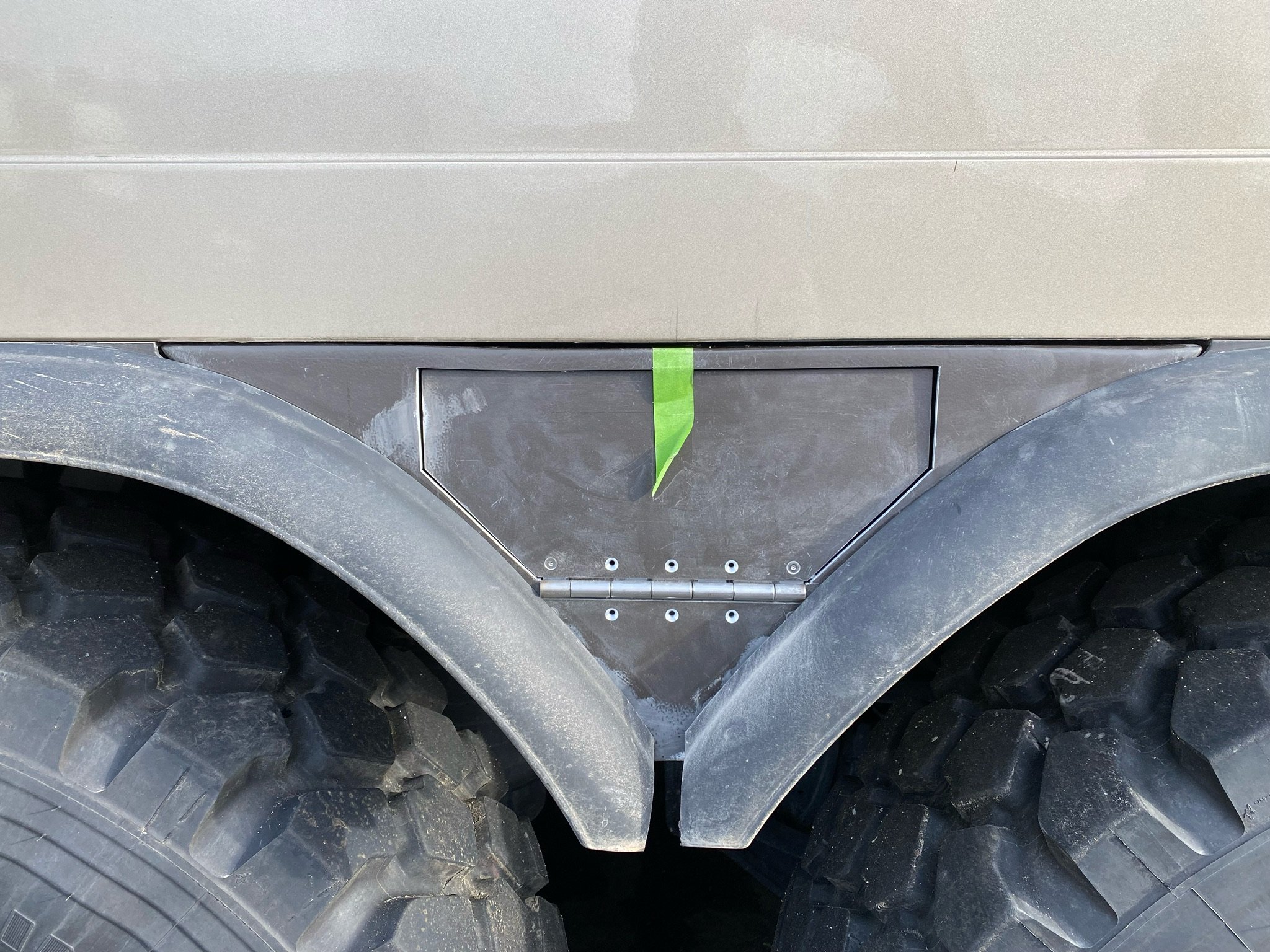
The rear wheels facia triangle are where we wanted the rear air hoses to reside.
Although the installation of the system equipment is normally quite simple, ours was a bit more complex because of where we wanted to position the hose bays. The front bays were simple, but the rear ones we wanted to mount inside a storage box housed between the two rear tires on each side. To do this we either had to manufacture the boxes, or repurpose the existing triangular facia covers that existed already in those locations. Since making new boxes would impact the wheel flares and mounting hardware, we elected to repurpose the existing facias. This was a major pain because of the incredibly poor job the body builder did in fabricating these parts. Nothing was straight, square or properly mounted to the underside of the cabin. So along with making the enclosures, we had to repair those facia triangles so they mounted correctly.
The other small challenge was where we could put the control panel. It needed to be close to the truck’s main air supply, but also where it would be protected. On our truck, this ended up being on the opposite side of the truck from the trunk line for the rear brakes, nestled underneath the cabin right beside the entry door and stairs.
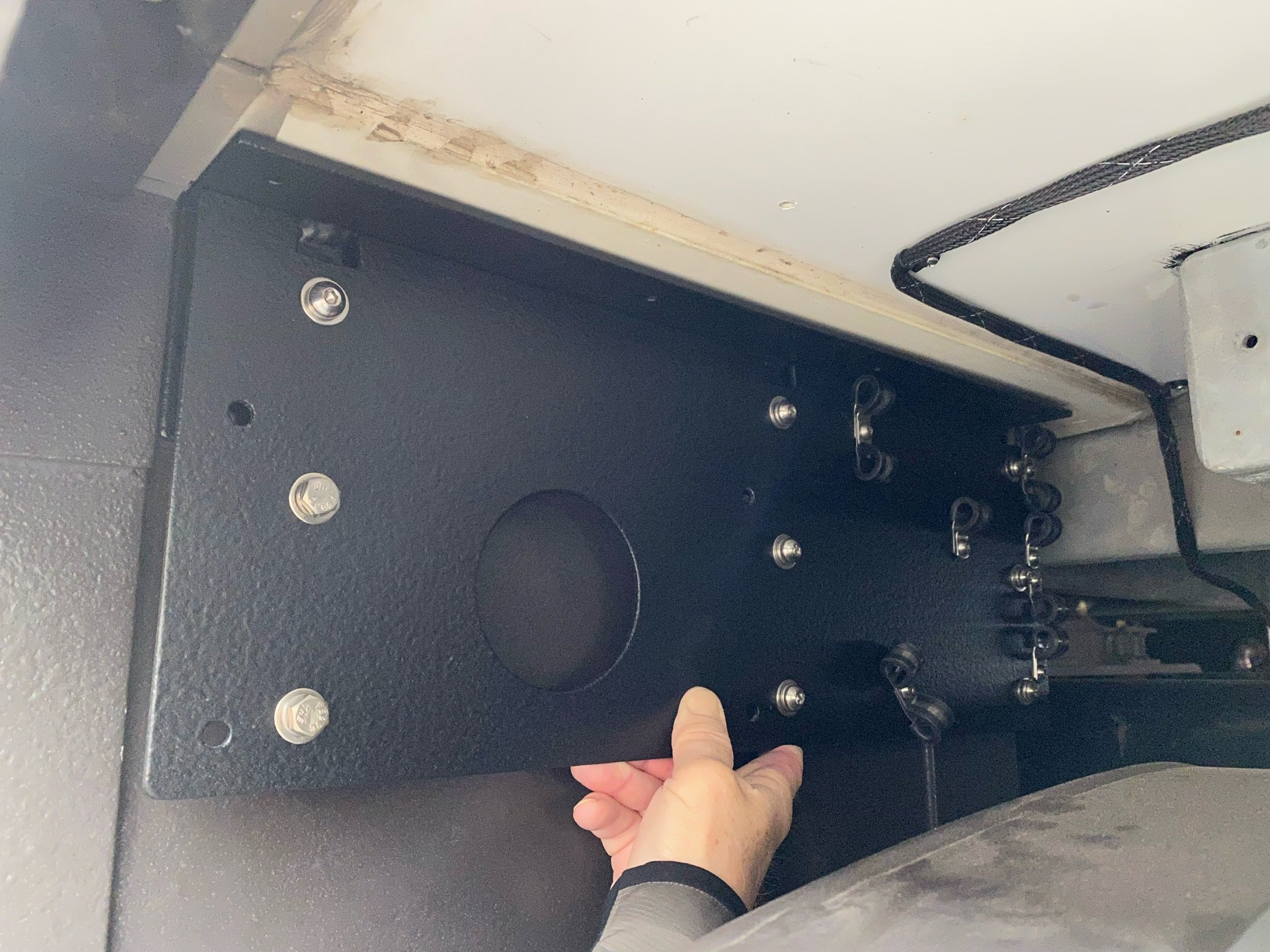
Step 1: CreatIng the mount for the control panel


The limited space on our truck exterior meant that we couldn’t use the control panel mounting bracket supplied by TI.Systems. So we had to design and manufacture our own.
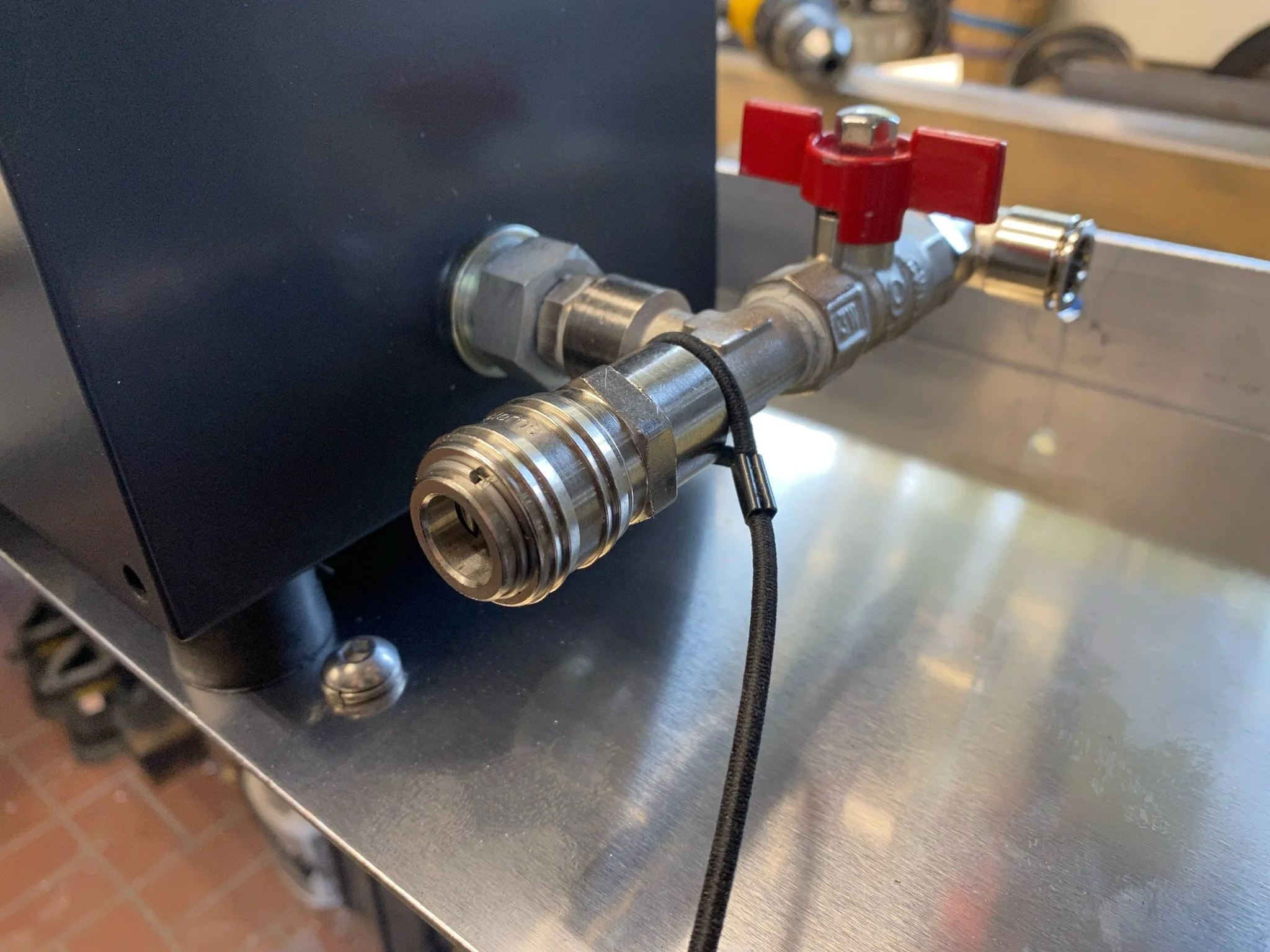
The control panel comes with an air outlet for a single air hose for operating air tools or inflating tires and other things, and also comes with four 12mm hose connections for attaching the supply lines to each of the six coil hose bays. We plumbed up the distribution manifold right on the control panel mounting bracket that we made. This made attaching each of the supply runs to the control panel much easier.


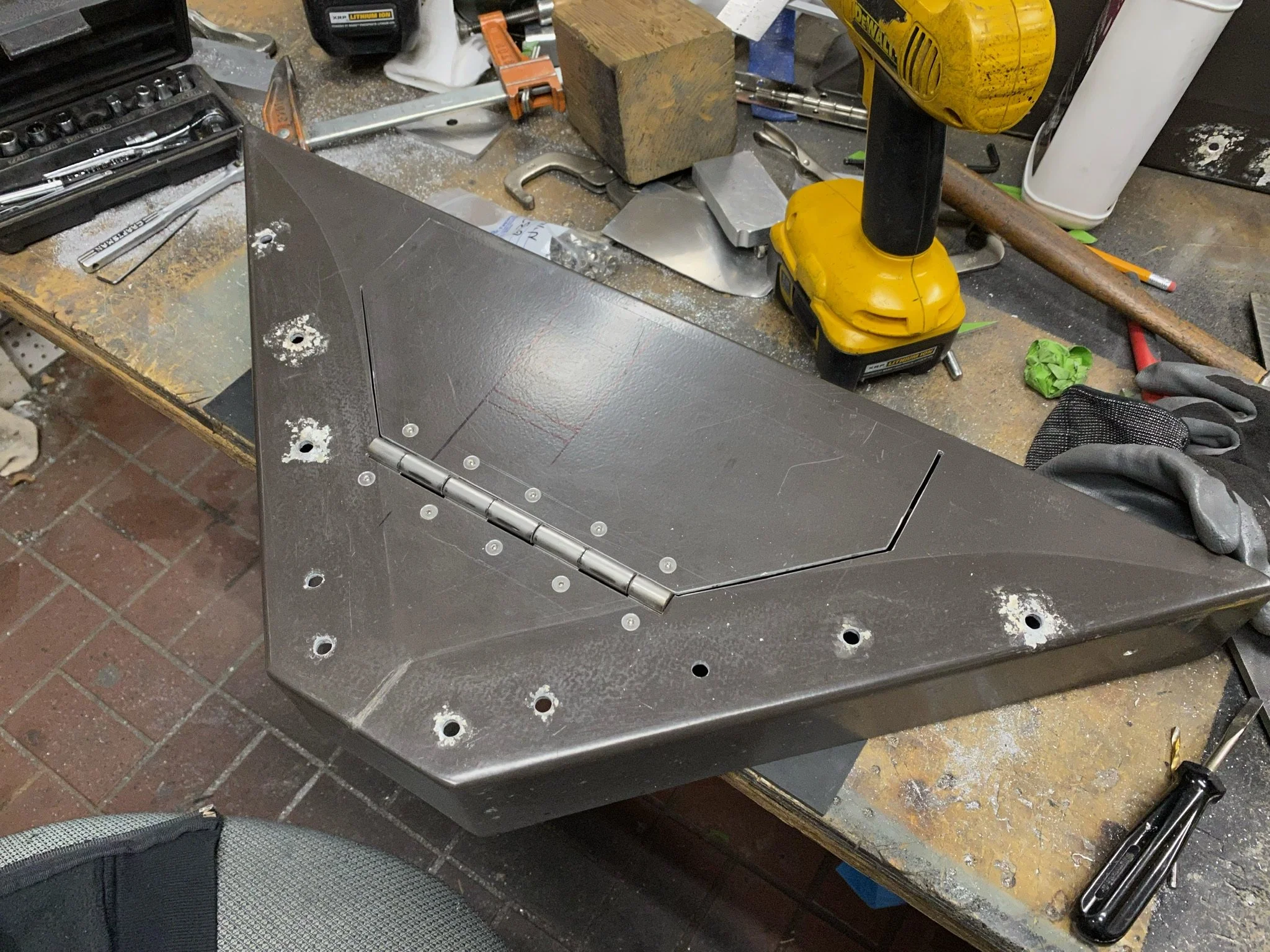
Step 2: Fabricating the rear hose lockers
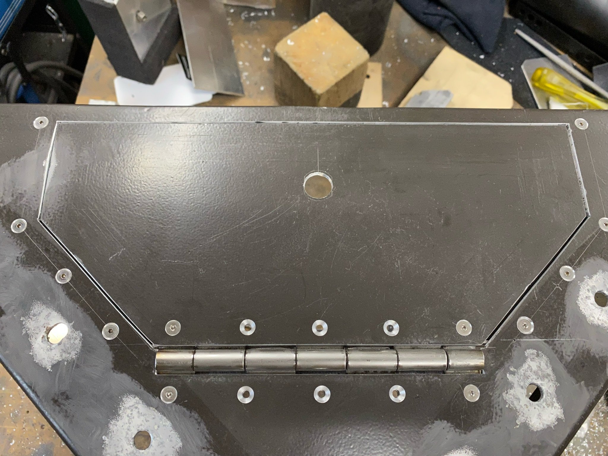
Attempting to build a waterproof box using an existing non-waterproof part.
A more tedious job than making the control box mounting bracket, the rear hose lockers had to be fabricated from light gauge aluminum and married up to the existing wheel well facia triangles. It was a challenging task as the triangles were poorly made with uneven angles and lots of distortion due to amateurish welding done by someone working for the bodybuilder.


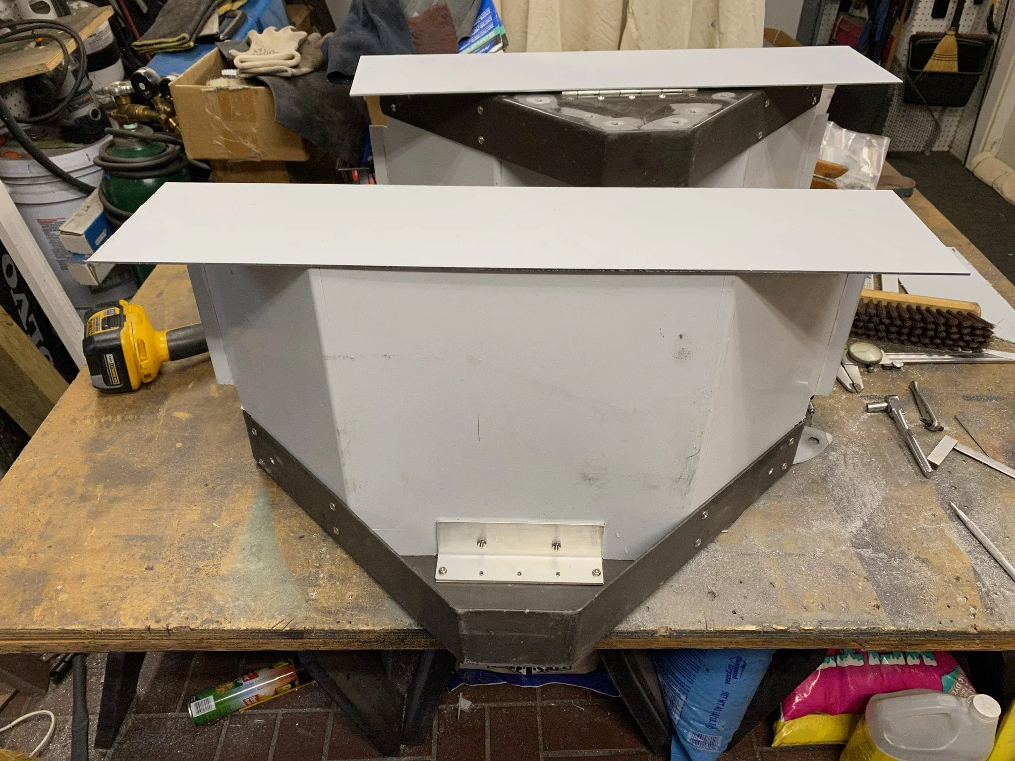
When constructing the enclosure pan it needed to interface with the facia triangles, the two-level stepped underside edge of the cabin box, and the hose containment tubes. Basically, it was a nip and tuck operation where each side was done individually because of the differences from one side to the other. One would expect them to be the same, but in our case that would be wishful thinking.


Since expedition trucks fall victim to vandalism and theft we had to fit door locks to the air hose lockers to protect them from unfriendly hands.


The final step in the completion of the rear hose lockers was to paint them. Rather than getting everything sandblasted and powder coated, most of which would get covered with gravel guard protection, we elected to simply sand the pieces to create a key in the surface for the paint, and then prime with an etching primer in preparation for the gravel guard and finished colour coat.


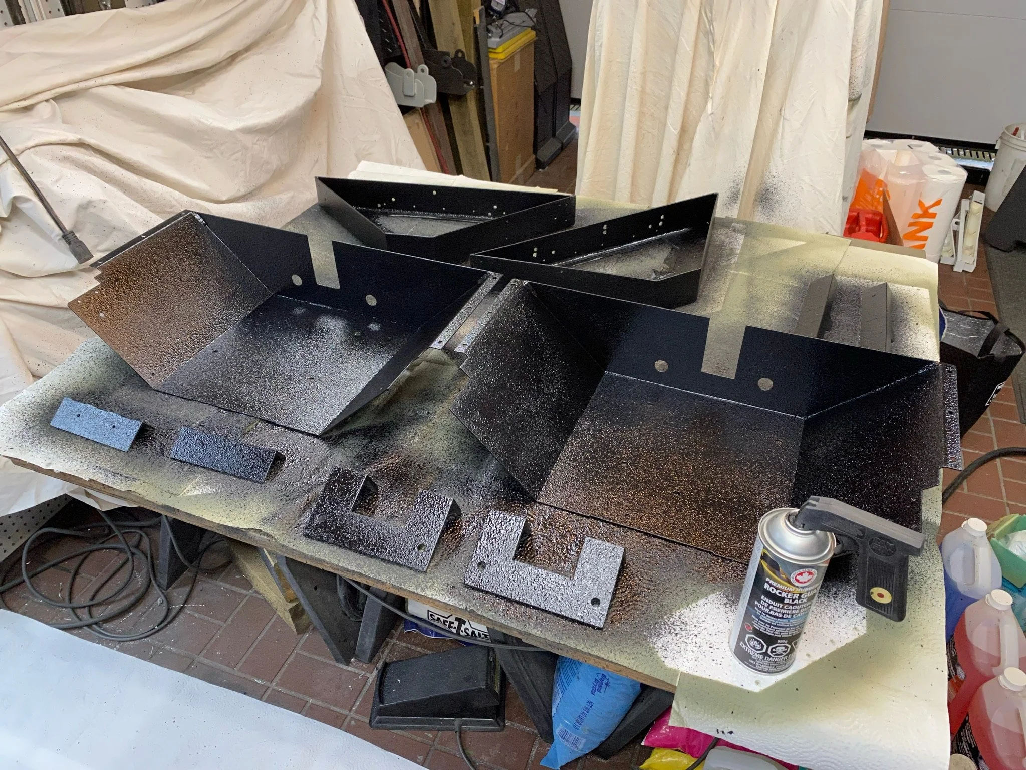


With all the painting finished and fully hard, the assembly process could begin. Through this process the other points of the enclosures where small leaks could occur are sealed up with foam rubber and caulking.


Step 3: STIS truck installation
The control box is located on the curbside of the truck just behind the fuel tank. It’s convenient, and on the safe side of the truck from the traffic.
Now that all the components are completed the final installation on the truck can be done. The first thing to install is the control box, as this is where all the air lines to the remote hoses begins, and from where all the airline lengths must be measured.
Next the air hose storage lockers and tubes need to be installed so the other end of the airline dimension was fixed. Then it was a simple task of cutting the airline to the appropriate lengths and running them along the frame.


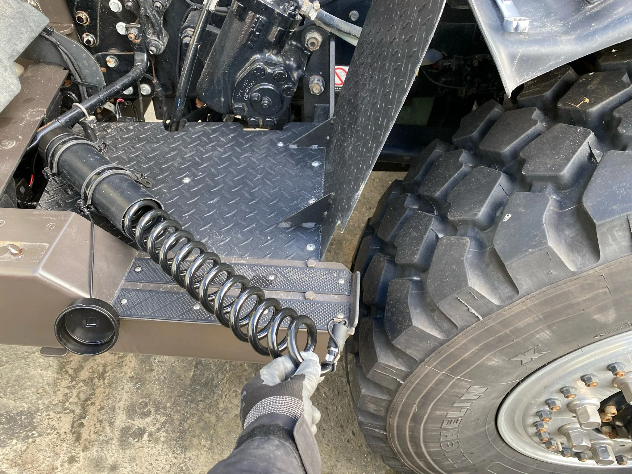
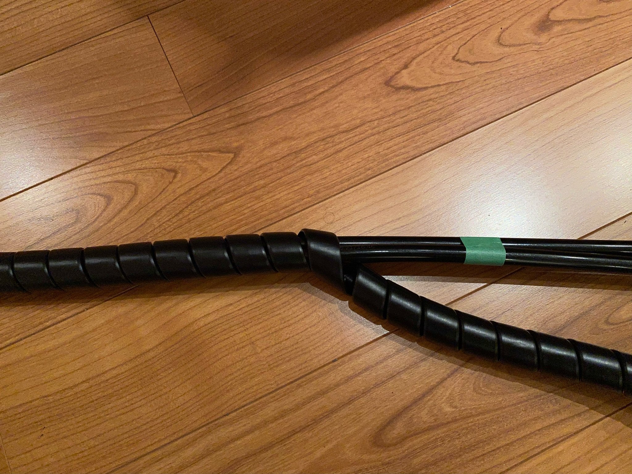
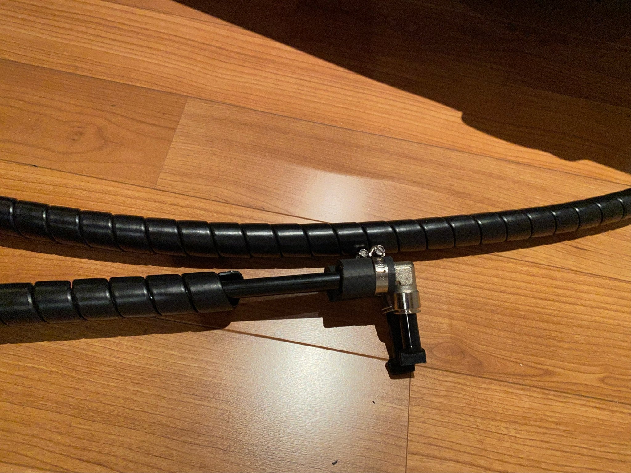
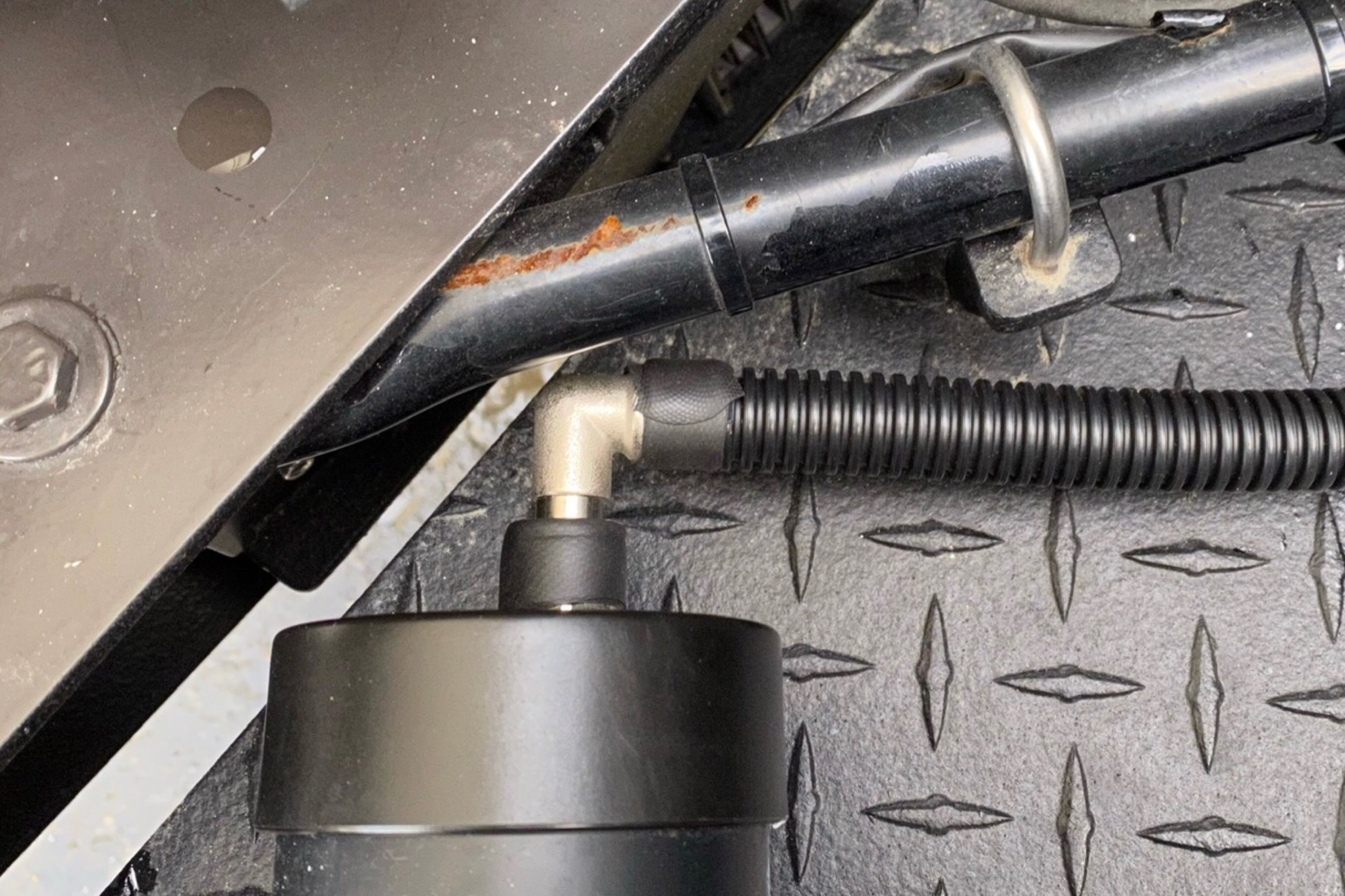
Now that the inflation hose storage units were installed we were able to determine the final route for the airlines along the frame, and consequently the final lengths of the airlines. Although the airline material is 12mm poly tubing with a 1.5mm wall thickness, and therefore very robust, we decided to wrap sections that would be exposed to abrasion or flying debris abuse with an industrial plastic spiral wrap material used for hydraulic and pneumatic hose protection. TI.Systems also provided a corrugated protection casing which we used in the wheel well areas.


Heavy zip ties and stainless hose clamps secure the airlines to the cabin subframe.
After the airlines were cut, bent and spiral wrapped, it was just a matter of feeding them along the frame rails. In the case of the front lines, the wrapped pair was actually fed inside the main truck frame rail, past the exhaust system and engine up to the very front. The rear lines were easier, fed just underneath the cabin box, behind the entry stairs and the generator. They were fastened to the underside of the cabin box with stainless steel hose hangers and stainless steel lag screws. When they reached the back they were fastened to the subframe with heavy duty zip ties and stainless steel hose hangers.


Step 4: The final process… tire vaLve replacement
8 wheels x 2 valves per unit wheel = 16 valves to install. Going to need a few cups of coffee for this one.
The last step in the process of installing the STIS on the truck was to install all of the special high flow tire valves in our Hutchison aluminum wheels. Since our Hutchison wheels are reversible, they have valve stems on each side of the rim. This means that we have to install sixteen valves, and to do the ones on the backside of the wheels, the wheels will have to be removed from the axles.
Our valve stems are not like those in conventional rims. Those valves are made with a rubber bulb at their base, and the valve is inserted from inside the rim and then pulled through from the outside until the bulb seats. Removal is as simple as using a knife to cut the base of the valve stem.
The 1/4”MPT Shrader tire valve on the back of our Hutchinson rims.
In our case, however, the Shrader valve stems in Hutchinson wheels are metal, and screwed into the aluminum wheel using a 1/4” male pipe thread. To change the valves we have to first deflate the tire completely to ensure that when the old valves are unscrewed, they don’t fire across the parking lot when the final turn of the thread takes place. Then it’s just a matter of cleaning the internal threads before screwing in the new valves with some thread locker/sealer.


All Complete And Ready For Use
Airing the tires back up from 0 psi, as we had to deflate the tires completely in order to swap out the old valves for the new ones.
With all the components installed, our system was ready for final testing. With the dozens of connections that were made from where the system was spliced into the main airline of the truck, to the terminus of each coiled air hose, there was a lot of potential for air leaks if we hadn’t properly sealed each threaded joint. Fortunately, we had no leaks. When we energized the STIS, and then closed the valve that isolates it from the truck system, the STIS held pressure overnight. So we were very happy about that. All we had to do to complete the job was to install the locks on the doors of the rear hose bays. We even found some weather proof caps to enclose the locks so they would not be damaged by the harsh outside environment of the rear wheel arches. A nice touch to finish off a rather time consuming addition to the truck.


