New Front Bumper
A Solid Replacement For the factory tin
The original factory bumper.
When we took possession of the Volvo truck from the dealer, we knew then that we would eventually need to replace the poor excuse for a front bumper supplied by Volvo North America.
Not only was the factory bumper nothing more than a cosmetic addition, but it was also impossible to add a winch or bull bar to. It was simply to superficial. It’s a common problem with North American built heavy trucks of all brands. Most get replaced by an aftermarket product made to take an impact from wildlife trying to cross the road, and defend the truck from damage.
The reason we didn’t go with an aftermarket product is that no such bumper existed for our truck model. Even if there was one, it would be made for highway use. In other words, made close to the ground, and therefore useless for off highway travel. To make things worse, these commercial products will not accept a winch for self recovery. This made it necessary for us to design and build our own.
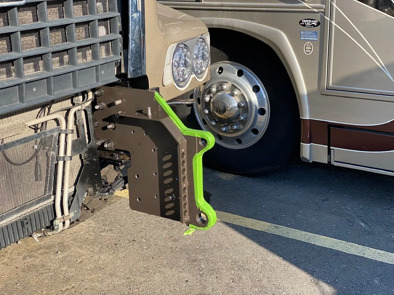
Our design for the bumper and bull bar. The bull bar must tip forward to service the engine.
Design Parameters
Most aftermarket “Class 8” truck bumpers are made from aluminum that’s nearly 1/2” in thickness. This is primarily to give the strength needed for the aluminum to withstand the force of an impact. And aluminum is used so it can be polished to achieve a chrome like finish. Something that North American truckers prefer, but we don’t. It’s a high maintenace item.
The problem with aluminum is that when this thickness is used, it pretty much negates any of the light weight advantages of the metal. Half inch thick aluminum weighs 6.98 pounds per square foot. The 3/16” thick steel that we used weighs 7.65 pounds per foot. So very close to being the same weight. Although steel is harder for us to work with in a home shop environment, it’s easier to weld. Aluminum is a great conductor of heat, and therefore transfers the weld heat away from the weld area very quickly, so a powerful welder is needed. Something we don’t own. Whereas steel is a relatively poor conductor of heat, so all the energy put into forming the weld pool is concentrated at the weld point. This meant our little 200 amp TIG welder would do just fine.
Modular Design
Irregardless of the metal used to make the bumper, it was going to be heavy. It’s a big bumper. Just moving it about in the manufacturing process at home would be difficult as the parts came together, as would installing it on the truck. So we opted for a modular design so the weight of each section could be more easily handled.
Right bumper wing, centre section, and left bumper wing. All bolted to the bumper brackets.
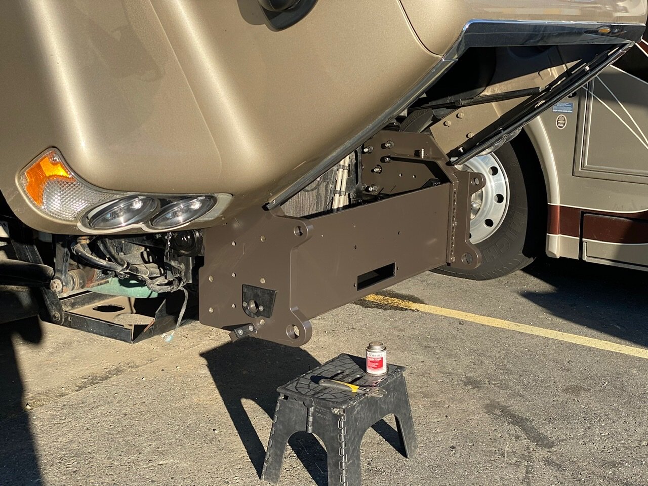
Complexity of the bumper brackets.
The bumper brackets bolt to the front end of the main chassis frame rails. These brackets are where the bumper wings, centre section, winch mounting channel and bull bar attach. Each part can be removed individually.
The modular design would also make repairs easier if the bumper ever took a hit. Only the section that was damaged would need to be repaired or replaced. This is an important factor since we couldn’t just buy a new bumper off the shelf somewhere.
The other advantage of the modular design is that the bull bar must be able to tip forward so the engine hood can be opened for service. It also allows for the bull bar to be easily removed by simply undoing the two main pivot bolts. This removal is sometimes necessary, as some countries like Germany, make having a bull bar illegal. Although visiting vehicles might be exempt, it’s always nice to have the option.
This shows how the bull bar can be tipped forward to access the engine compartment.
Measure Twice, Cut Once
This old saying is very appropriate for this project. Since work is being shopped out to others at a significant cost, we needed to check, and double check, that what we envisioned was actually going to work. Despite designing on a CAD program, nothing provides a better illustration of the finished product than doing mockups with easy to work, inexpensive materials. In this case, that meant printing off full size drawings of critical parts and laminating them to cardboard. Then they could be fitted onto the truck for verification.


The Build Begins
Unlike other projects we have undertaken, this one will require a greater amount of work being done by commercial shops. The steel is the primary reason for this. Unlike aluminum which can be cut and shaped with wood working machines, steel cannot. So cutting and bending the fender skins, and bumper brackets had to be farmed out to two different metal fabrication shops.
We start with the foundation… the bumper brackets


Like all construction, you have to start with a good, strong foundation. In this case, that would be the brackets that attach the bumper and bull bar to the truck’s frame rails. They take all the force from either impacts or recovery winching. And when you’re pulling a 19 tonne truck out of a sticky situation, that can be quite a lot.
The bumper brackets were made from 5/8” thick steel, and were a complex shape. So they needed to be cut in a way that wouldn’t stress the metal and cause it to warp. This meant no heat. High heat imparted into steel by cutting torch, plasma cutter and even laser can cause it to distort, and the last thing we wanted was 5/8” plate that wasn’t flat. So our cutting method of choice was waterjet abrasive cutting. It provides a near perfect cut by injecting an abrasive material into a high pressure stream of water that does the cutting with zero stress imparted into the metal. It’s also very accurate, cutting to tolerances of .005 inches. The bonus from this is that we didn’t have to drill the holes, not even the ones that had to be threaded. The water jetting could do it all for us.
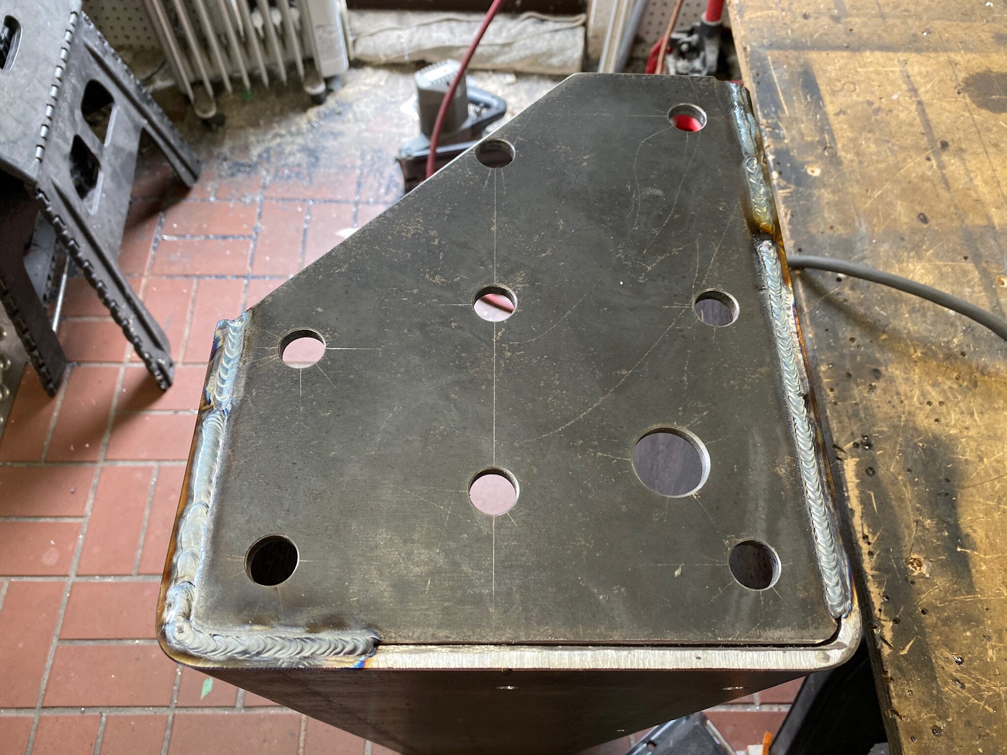
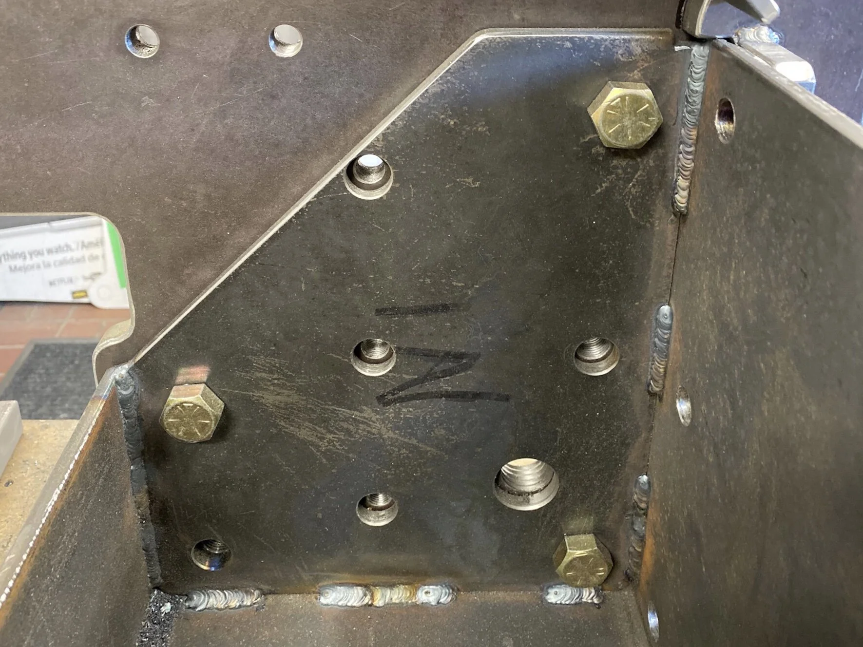
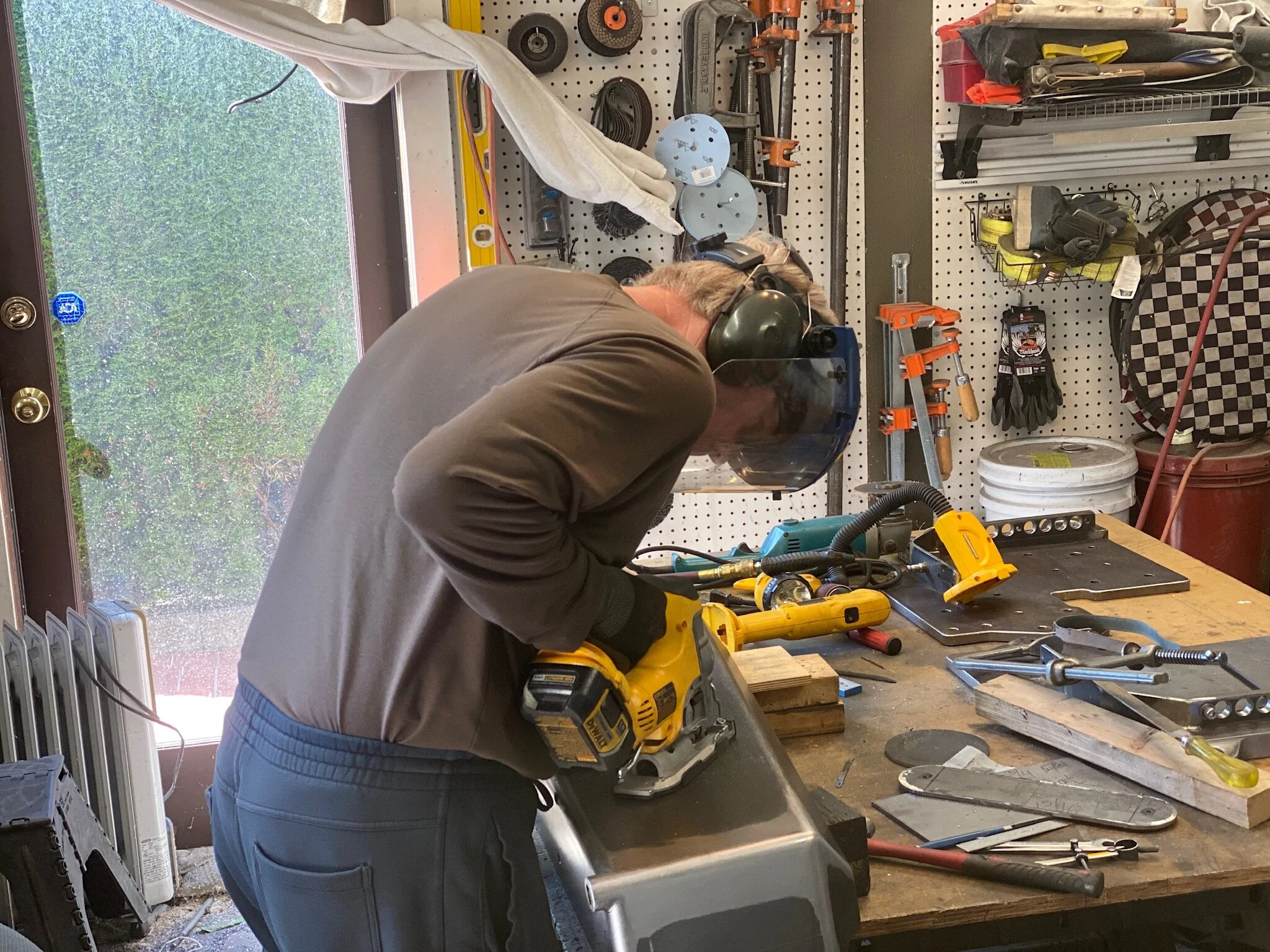
Threading the 1” holes required adding pipe extensions onto the tap handle to get enough leverage to turn the coarse thread tap.
This is significant as each bumper bracket has nineteen holes. Although drilling holes in a steel plate using a drill press isn’t necessarily that difficult. The challenge comes when you only have a small drill press with a small table, and you’re trying to hold a 20” x 28” plate weighing 60 pounds. So pre-cut holes are always welcome. Unfortunately the water jetting couldn’t tap the holes for us. So we had to do it. The bulk of the holes were not too difficult, being 1/2”-NF and 5/8”-NF threads. However, one hole was larger, needing a 1”-NC thread. There were only two of these, but they were still a grunt to complete.
Once the holes were all tapped, the next step was to laminate the two bracket components together so the double thickness recovery points could be created. But there was a small catch. The upper recovery point was for smaller shackles, and they couldn’t fit over a 1-1/4” thick plate. So the smaller component had to be machined to make the upper point thinner. This was done on a table saw using a special blade made for cutting ferrous metal. It was the first time we had used this kind of blade, and we couldn’t have been more impressed. The Diablo Steel Demon ceramic carbide blade was amazing.


Laminating for thickness
Before the two water jetted components could be laminated together for the recovery point thickness, a piece of steel flat bar had to be machined and welded to the smaller component. This piece does two things. The first is to provide the bolting locations for the centre bumper skin when it is installed over the winch channel, and the second is to provide the support brace against which the winch channel will pull against when the winch is in use.


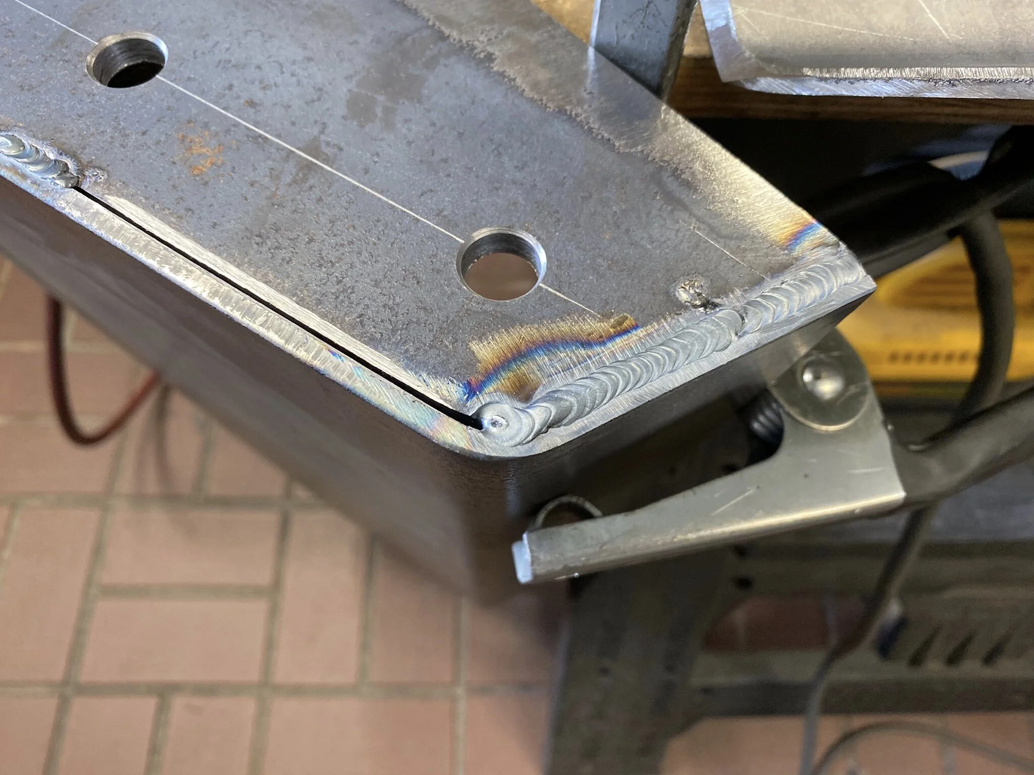
Laminating the two plates together start by grinding a chamfer along the edges of the two parts only in the location where the continuous weld would be placed. Once done, the two pieces are clamped very tightly together to ensure no gaps are present where water might ingress and start corrosion. Then a continuous TIG weld is laid into the V-notch created when the two plates are clamped together. The weld only runs around the outside perimeter of the plates, and does not run along the flat of the large plate behind the add-on piece. Doing so would cause that main plate to deform out of plane along the length of the weld. Something we don’t want to happen.


Dressing down the perimeter weld was essentially done by hand using a small angle grinder and then a hand file. Working old school is time consuming, but since we only have a small garage workshop and not a production shop, it’s the reality we must deal with. The upside is that these skills were learned many decades ago, and like riding a bike, are skills one simply doesn’t forget.


The Winch Mount
Bridging the gap between the two bumper brackets, and forming the structural point at the front of the truck for the Sherpa 25,000 pound winch, the winch mount was made of 5/16” thick steel plate that was bent into a channel. It will also serve as a storage compartment for recovery gear and other items that need to be close at hand.
Bent by a heavy fabrication shop, the final product had some issues that we had to deal with. The between leg dimension of the channel was 1/8” wider than specified, which wasn’t a big deal. But one issue that presented a problem was the out of square ends on the channel. They were out over 1/8” across a 10” span. In our experience, that’s a lot. It created a parallelogram which increased the length of the channel beyond the allowable dimension.


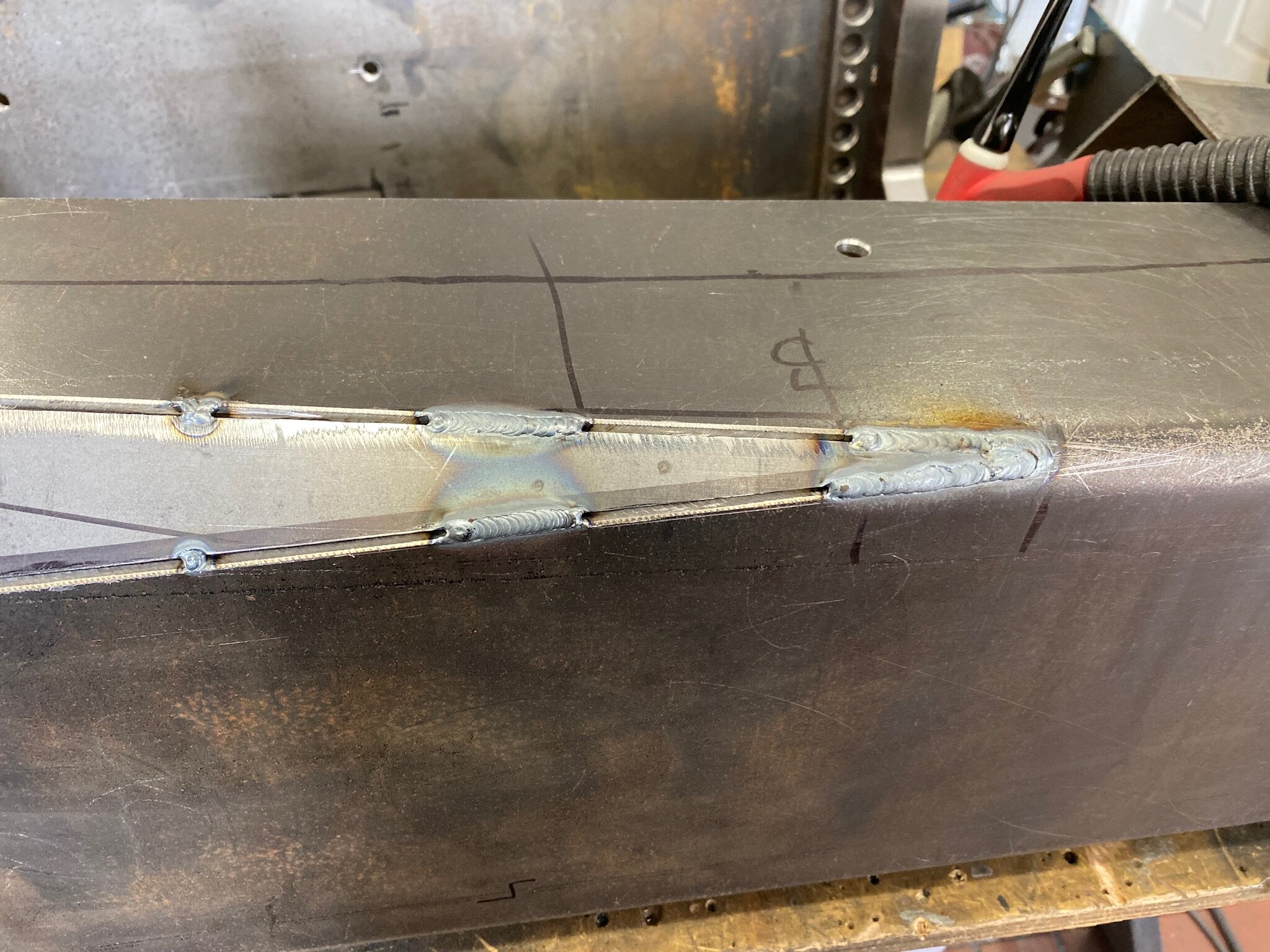
Although both ends were out of square, we only had to trim one end to bring the channel back to the correct length. So the opposite end, that was still un-square, had to be wedged while the end plate was tack welded in place.
Once everything was tacked in place, the welding could begin. Because of the extra front to back depth of the channel, the end plates that we had the fabrication shop shear for us were now too narrow. So we had to equalize the gap around the perimeter, and then fill them with weld metal.


Once the end plates were welded on, the hard part was next. That’s the process of cutting in the winch opening on the front face. This was done using the Steel Demon circular saw blade in a skill saw, a steel blade in a jigsaw, an angle grinder and hand files. Nevertheless, 5/16” (8mm) steel is tough to machine with hand tools.


Bumper Centre Skin
The centre skin performs two functions. One is cosmetic, for the look of the bumper. The second is more functional, as it helps to enclose and secure the winch and storage area.
Another of the parts bent up by the fabrication shop, we ordered the formed shape fully knowing that we would be taking a saw to it in order to create the final part. It was a better way than trying to work with flat pieces and attempting to blend the joints to get the same look. The key was the 3/8” radius on the bends. We wanted them to match the radius on the bends of the bumper skins.
The Steel Demon blade makes short work of the 3/16” bent plate.
The first step was to remove some of the bottom face metal. Further consideration after ordering the parts was that we could remove some weight by reducing the return dimension when the centre skin wraps around the underside of the winch channel. At the same time this extra metal was sawn off, we also made the cut for where the hinge for the opening lid would be.


This not only shows the notch detail for the hinge, but it also details the cutout needed on the end for the double thickness section of the bumper bracket.
To finish the centre bumper skin we had to add the components to the bumper brackets that the hinged lid would mate up with. For this purpose, 1/4” x 2” flat bar was bent and then fitted to the profile of the bumper bracket. It was then drilled and tapped for bolts that would hold the rear closure panel on, and also drilled for the lock mechanism and latching knob.


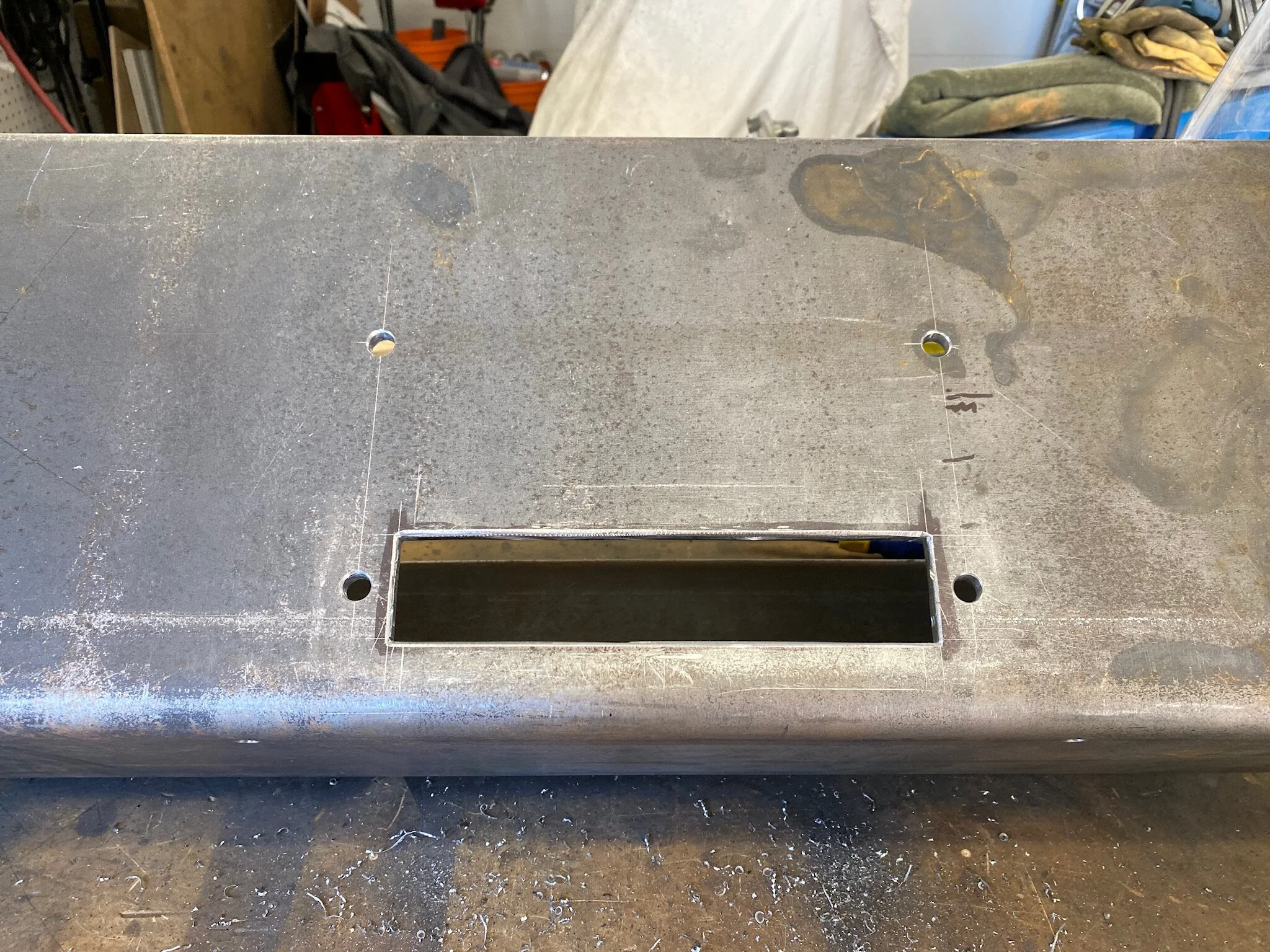
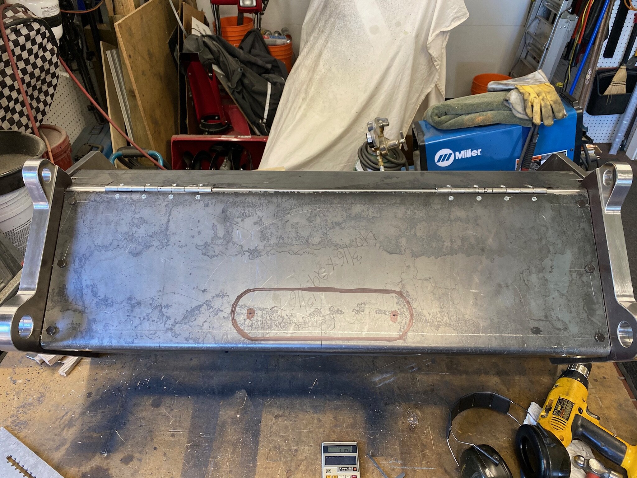
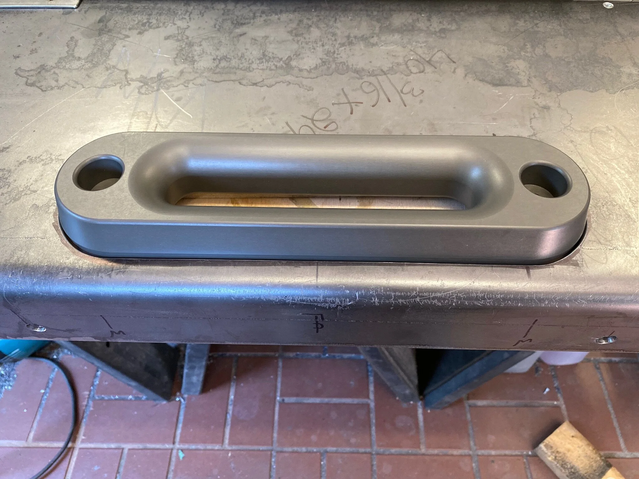
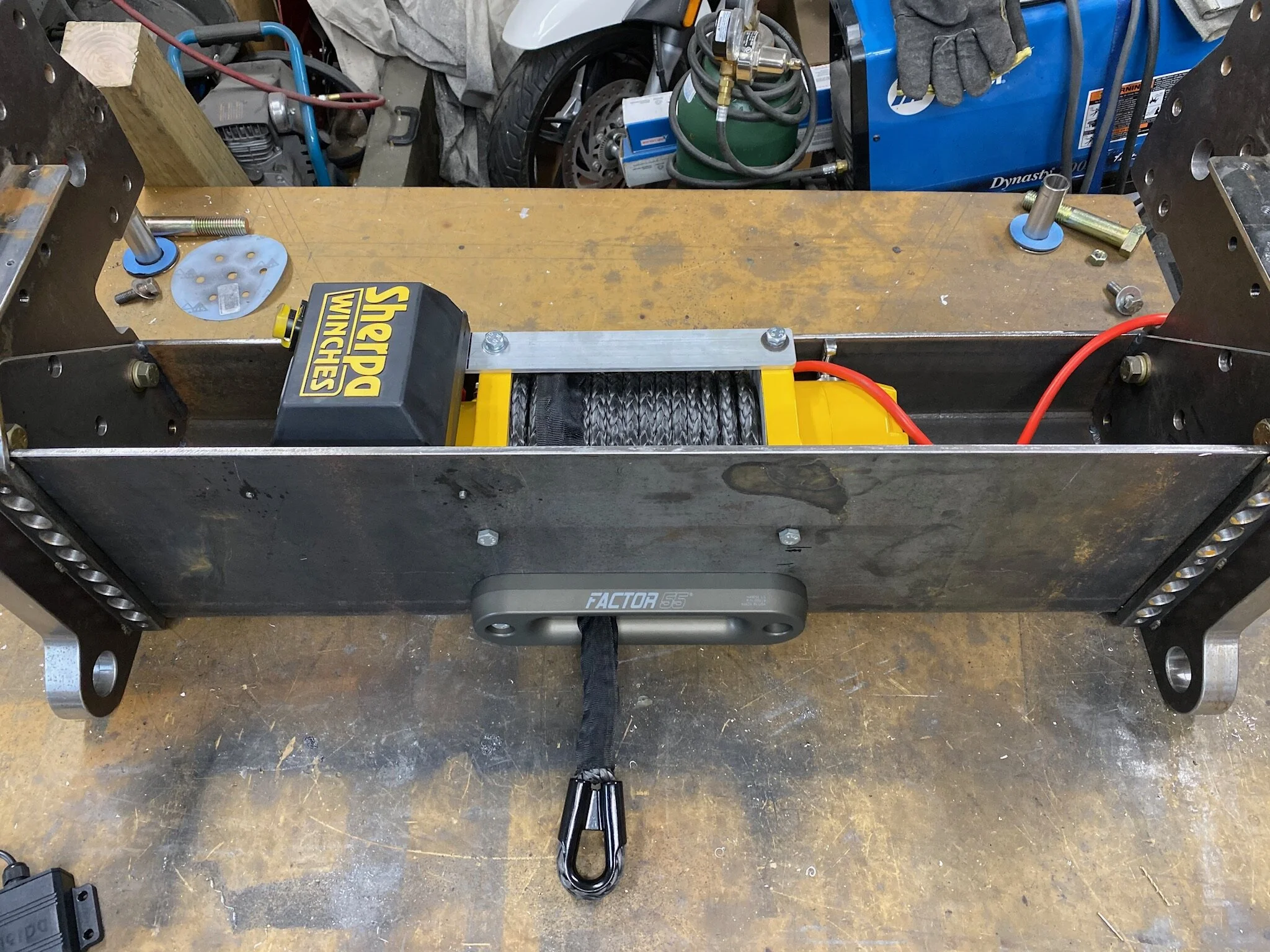
The last thing to do to the centre bumper skin was to create the cutout into which the Factor55 fairlead will sit. The fairlead needs to be mounted solidly to the winch mount proper, rather than to an overskin. This way it can withstand the extreme forces from the winch line without any chance of moving.
At the same time the screw holes for the front license plate will be laid out and drilled. This way the front facial will be totally finished.


Now for the complicated part, The bumper corners
Up to this point, despite the weight and thickness of material, all of the components made so far interact with each other at right angles. So that makes construction fairly easy. The bumper corners, however, are complex shapes and don’t have a square joint anywhere.
What makes things more challenging is that the bumper corners conflict with the truck hood when it’s tipped forward to access the engine. Our new design protrudes further out in front of the truck than the factory tin, which means several fittings on the truck would be needed to figure out how much of the front face would need to be relieved so the bottom edge of the hood would clear.
Creating the corners began by taking the various brake shapes and mitering the ends that would eventually be welded together. This was done using a combination of the skill saw with the Steel Demon blade, an angle grinder with a zip disk in it, and on occasion, a hand jigsaw.
Since the two sides are simply mirror images of each other, it was easiest to do the detailed layout on one side, and then after cutting and finishing it, lay it onto the opposite side blank and trace the outline with a scriber.


Side Skin With Integrated Step
By far the most detailed part is the section of bumper that stretches down the side of the fender toward the front tire. Aside from the miters at the front corner, it also has to be cut to feature the integrated step that will allow easier access to the top of the engine and the more frequently needed reach to the windshield.


At this point I should give credit where credit is due. The idea of the side step is not a Foster original. I borrowed the concept from two European designs, one from Mercedes Truck In Germany, and the other from Action Mobil in Austria.
The step cutaway came from the Mercedes Zetros, which is a truck we dearly would have preferred over the North American Volvo, as it comes fully equipped for offroad use. But we couldn’t get it because of the stupid North American protectionist rules.
The swing down step came from the world renown expedition truck builder Action Mobil. It’s a solution they developed to solve the problem of trying to climb up into the very tall European offroad trucks they use. Combining the two ideas gave us a nice solution for our access problem.
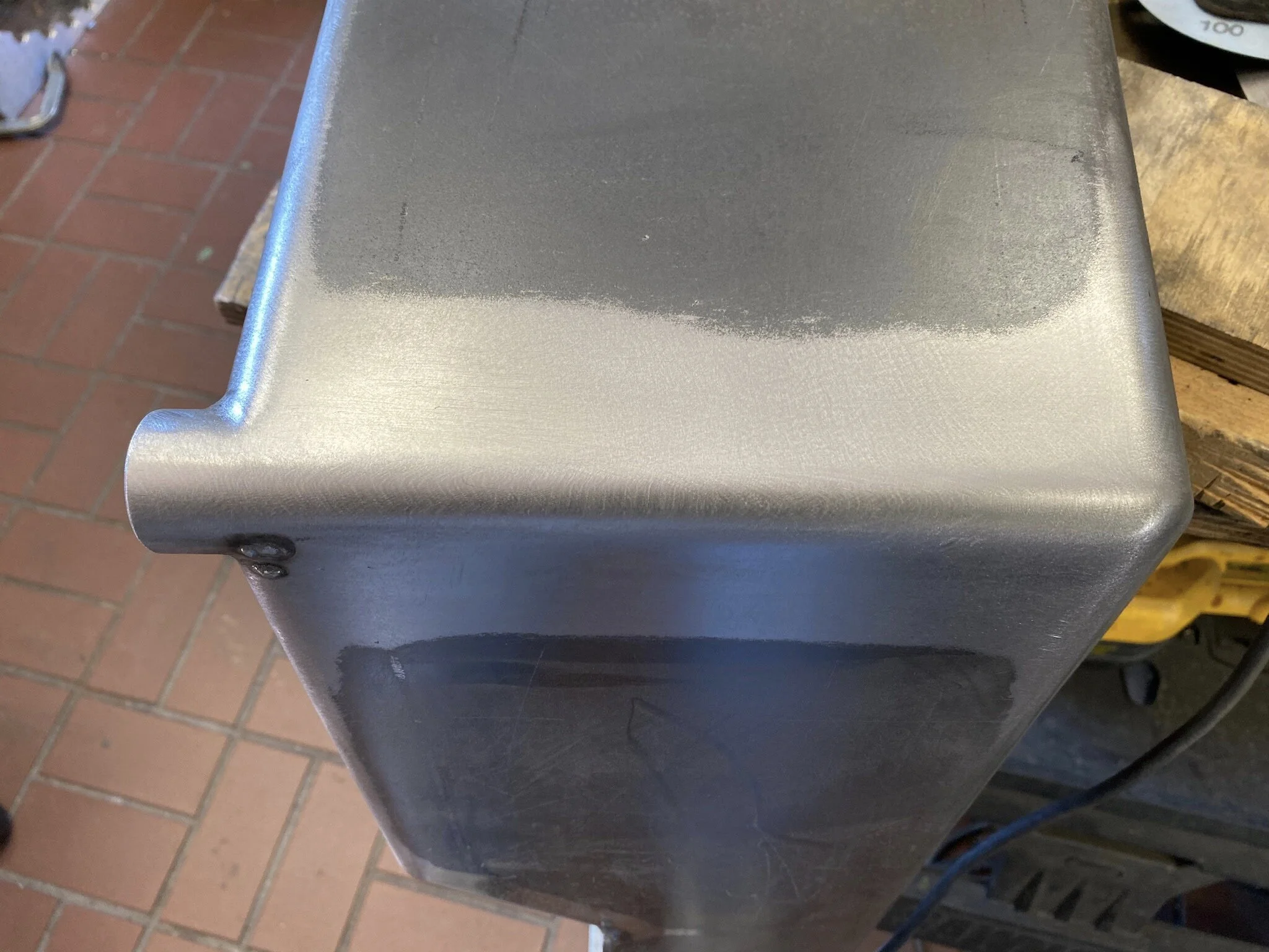
Properly blended joints look just like the bent edges of the part. Can you tell which is which?
The side skin is where the more difficult and time consuming work takes over. Not only does it involve simple fabrication, but it also requires the fine blending of visible joints so they become invisible. The part should look like it was somehow pressed out of a single sheet of metal without welded joints.


Before finishing the side skin step area, we shifted to joining the side skin to the front face of the bumper. There would be a lot of manual manipulation of the corner assembly for verification on the truck, so delaying the addition of extra weight during this process is desirable. It’s also better to have as much three dimensional reinforcement as possible before adding the step material. There’s a lot of welding in the step, and this causes distortion. Not something we want to then have to marry up to the front face. Better to work with two pieces that want to fit together, rather than trying to bend pieces back into shape so they match.


Fitting the parts on the truck
Now that the corner assembly has been joined together and mounting plates attached, we were able to do the necessary trial fitting on the truck. This fitting was needed to ensure our angle calculations were correct so the side skin aligned with the side of the front fender. We also wanted to check that the side of the bumper protruded out the side of the fender just the right amount so it lined up with the fender flare. The protrusion was also important because this is where the anchor plate for the bull bar outrigger would sit.


We also needed to determine how much of a relief cut would be required on the front leading edge of the bumper so the hood would clear it when opened.


After the relief facet was finished, a test fit showed the hood cleared the bumper by 1/4”.
Finishing the corner connection
The 1-1/4” corner bar is more than cosmetic.
With the relief cut for the hood clearance finished, and the test fitting on the truck to confirm all our angles done, we were now able to finish the joining of the front face with the side face. This was not only a structural connection, but also the most visible cosmetic point on the bumper… the outer corners.
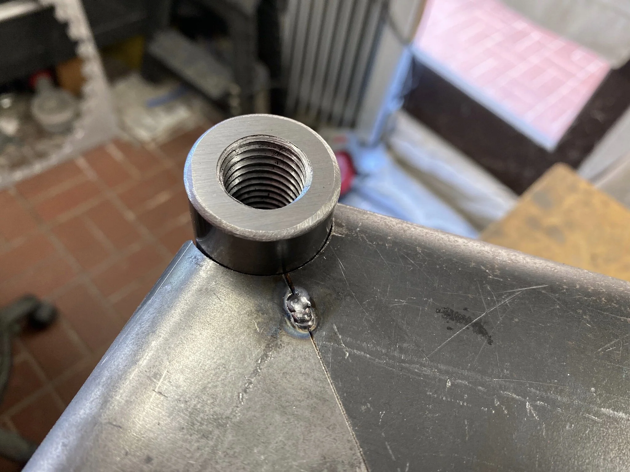
Blended into the corner was a length of 1-1/4” diameter solid round bar that was drilled and tapped on the upper end with a 3/4” coarse thread. This would be the main pivot point for the locking mechanism that secures the bull bar in place. It also provides the cosmetic curvature to the vertical mitre joint so it matches the radius of the bends along the length of the bumper.
The challenge here is the gap that’s created by the radius of the round bar and the cut in the bumper face. It’s much longer across the weld joint than a simple fillet weld if the objective is to make the joint look seamless. A lot of filler metal must be laid down, only to then grind a lot of it off in order to make a flush joint. Working with square material would be so much easier, but in this case, round was the only option.


Completing the side step
The final fitting on the truck so we can test to see that the tires clear the bumper end when the wheels are turned.
The last step in enclosing the bumper skins was to create the step area at the rear of the side skin. This would finish the structural part of the bumper corners, under which would be mounted the swing down step. The step surface will also be the attachment point for the rear bumper bracket that mounts on the side of the frame braces the side assembly.


The convenience of a foLd down step
The bumper side step is 33 inches off the ground. It’s a side effect of having a Class 8 heavy truck, set up for off highway travel. So to make things easier, the fold down step was incorporated under the side of the bumper to halve the 33 inch distance to a more manageable 17 inches.


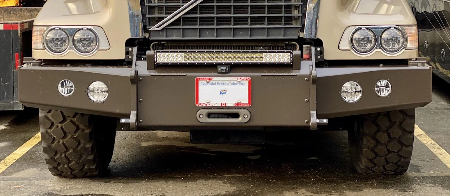
Adding auxiliary lights
Paper cutouts are used to decide on position.
One of the biggest challenges with all our vehicles over the years is that of having decent light when traveling at night, on highway or off. So for this build we’ve incorporated the latest lighting technologies from several of the top vehicle lighting manufacturers.
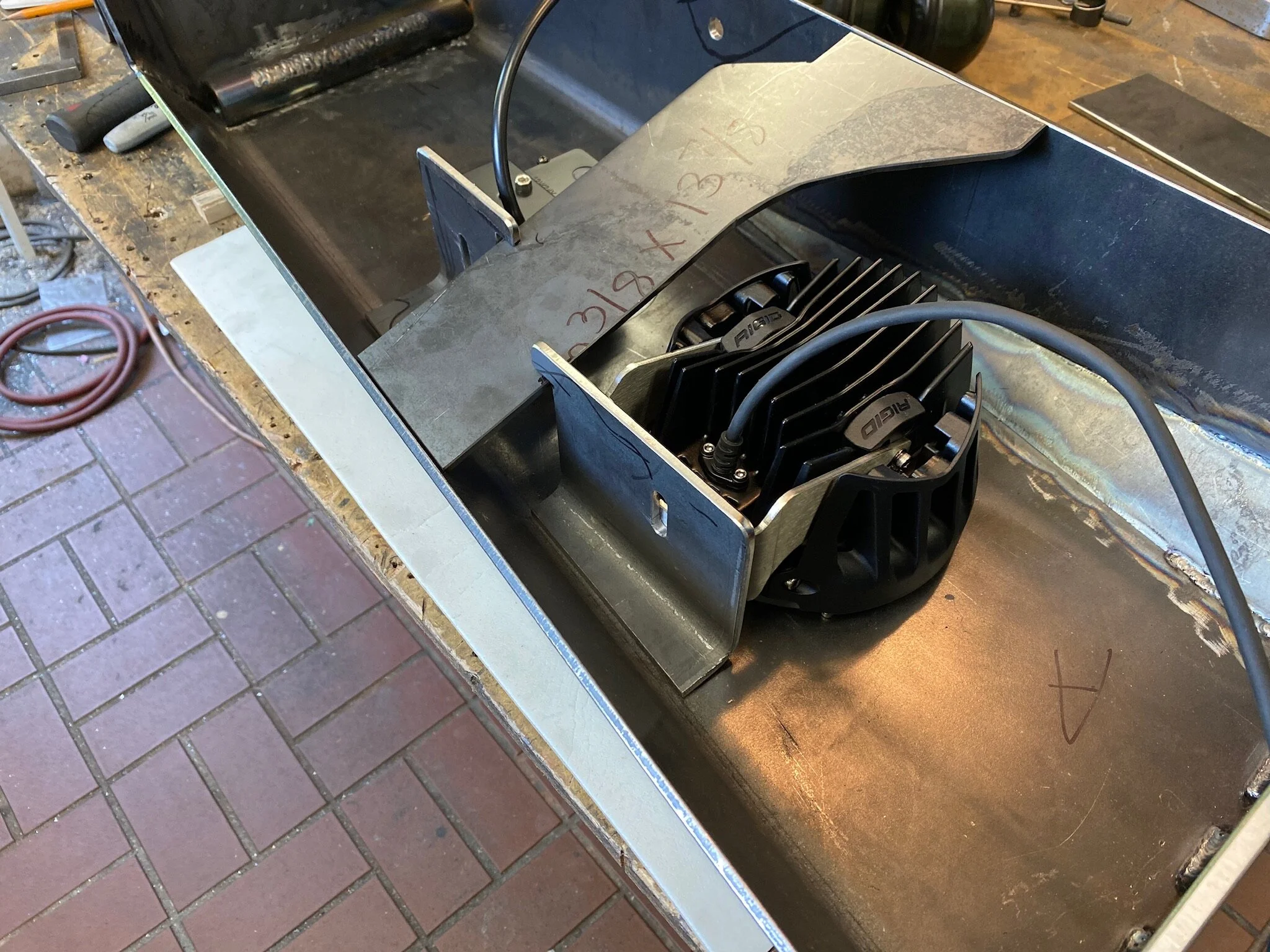
The main-off highway light is an E-Series Pro 30” light bar from Rigid Industries, configured in a flood/spot combination. It projects over 32,000 lumens out to over 1300 meters. It’s essentially a small sun sitting on the top of the bumper.
To provide extra on-highway lighting that’s legal to use, we added a pair of Rigid 360-Series configured as driving lights. They provide over 8,000 lumen, and cast light out past 500 meters. A nice addition to the J.W. Speaker LED headlights we installed to replace the pathetic halogen sealed beams that came with the truck.
Lastly, for replacement fog lights to those supplied by Volvo, we chose the KC Hilites Gravity LED G4. They’re a 4” light that provide a broad low level beam for seeing clearly over short distances. Something that is definitely needed when traveling at certain times of the year, especially at night. Our worst fog experience was in our Class A motorhome traveling over the Pendleton Pass in northeastern Oregon in January. It was night, and the fog so thick that we could barely see twenty feet in front of us. The only way we could stay on the road was by watching the lines on the road. It was a 10mph trip until a logging truck passed us going much faster. We figured he must know the road well, or was using a technology we didn’t have that allowed him to travel faster, such as a FLIR system. So we sped up and stayed right on his tail. We figured as long as we could see his taillights, and those taillights didn’t suddenly jump way up in the air and then disappear, we wouldn’t be following him off a cliff. Fortunately, it worked out fine and we cleared the fog on the eastern side of the pass.


Final bumper supports
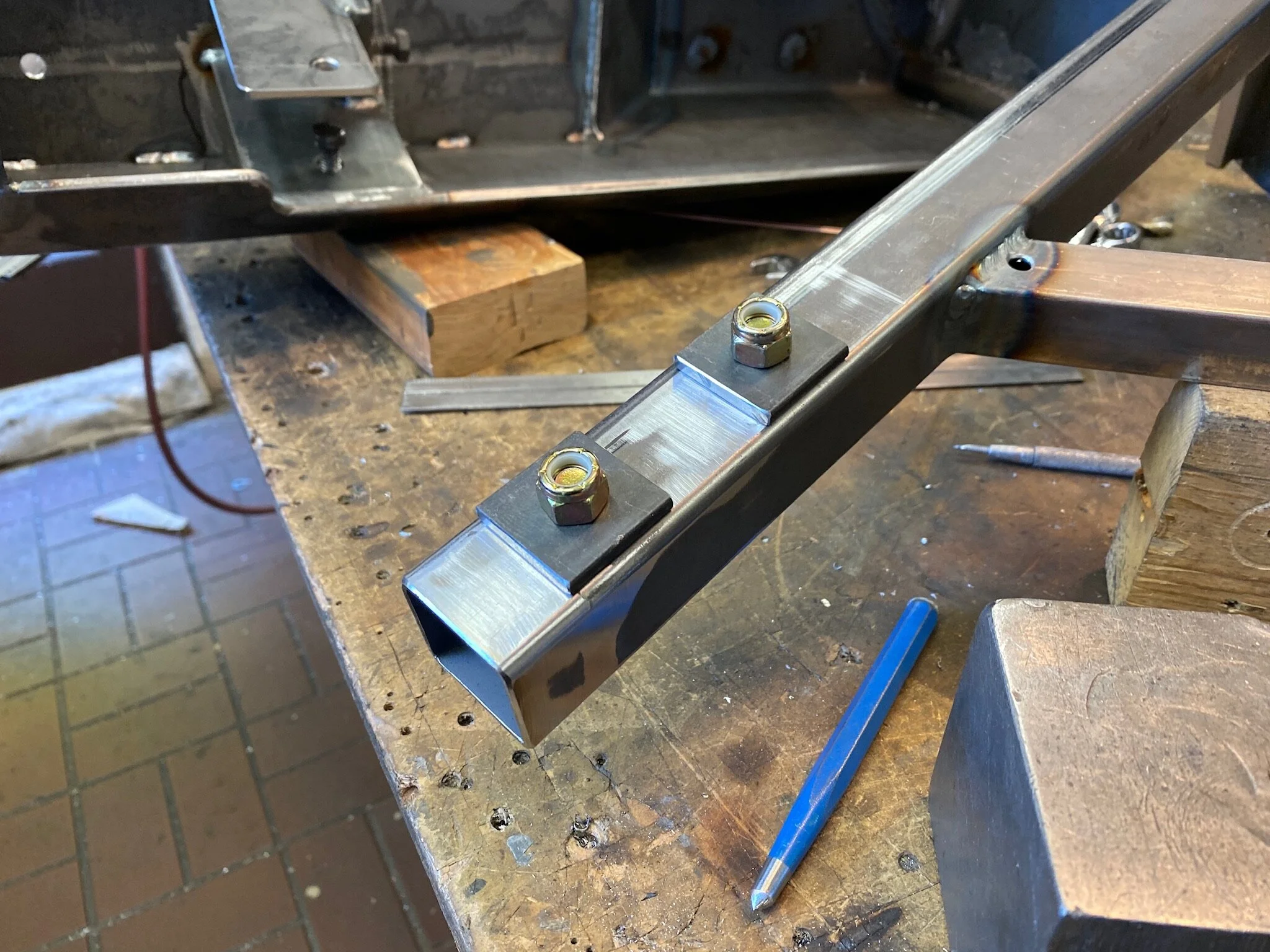
The last thing to do before moving on to the bull bar part of the build is to create the rear bumper supports that tie the step area to the truck frame. We’ll be using the existing mounting bolts that hold the two steering boxes to the frame. The steering boxes are held on with three 20mm bolts, and we’ll be using two of these on each side.
The side wing of the bumper is strong, but the length of it allows tremendous leverage if forces push in against it. So it needs help to keep it from being pushed inward and downward. But it still needs failure points in the case of a collision, so they are built into the outboard end of both struts that attach to the front corner point and the rear step area.


One last bit of steel work
The last things required for the bumper are locks for the bull bar. Since the bull bar must tip forward in order to open the hood for engine access, something needs to be created to lock the bull bar firmly in place for travel. We weren’t able to find any commercially available locking devices that would suit our need, so a unique solution had to be designed and created.
The pivot lock did more than just lock the bull bar in the travel position. It’s also the device that holds the outrigger bar and vertical end plate firmly to the steel bumper if it was to take a direct impact of a substantial nature. That’s why it needs to be so beefy. To accomplish this it works in conjunction with two 1/2” pins that are welded to the top surface of the bumper and key into corresponding hole in the baseplate of the outrigger vertical end plate.
The lock mechanism swings over the front of the wing vertical plate base, and is secured to the bumper via a grade 8 bolt.


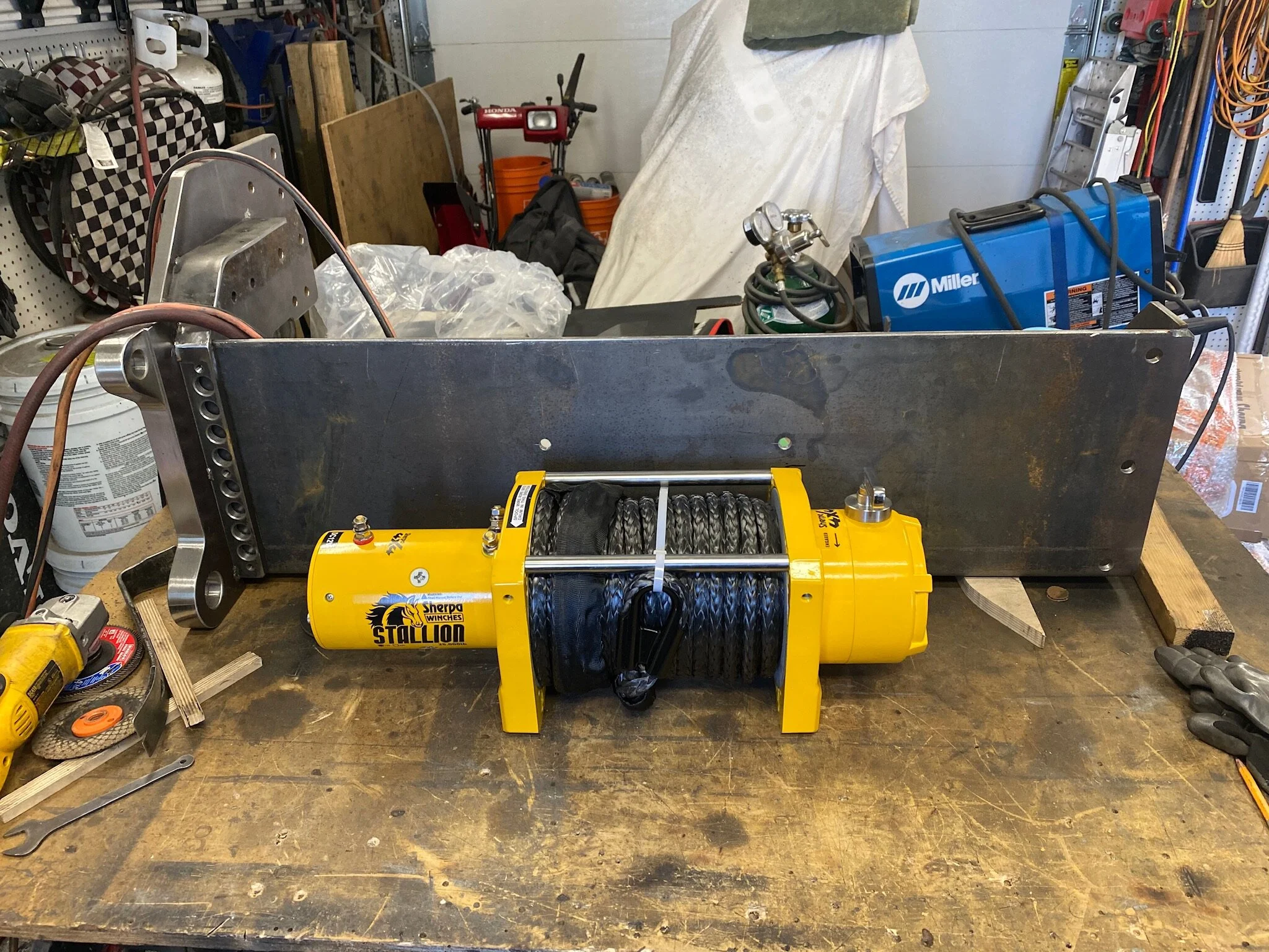
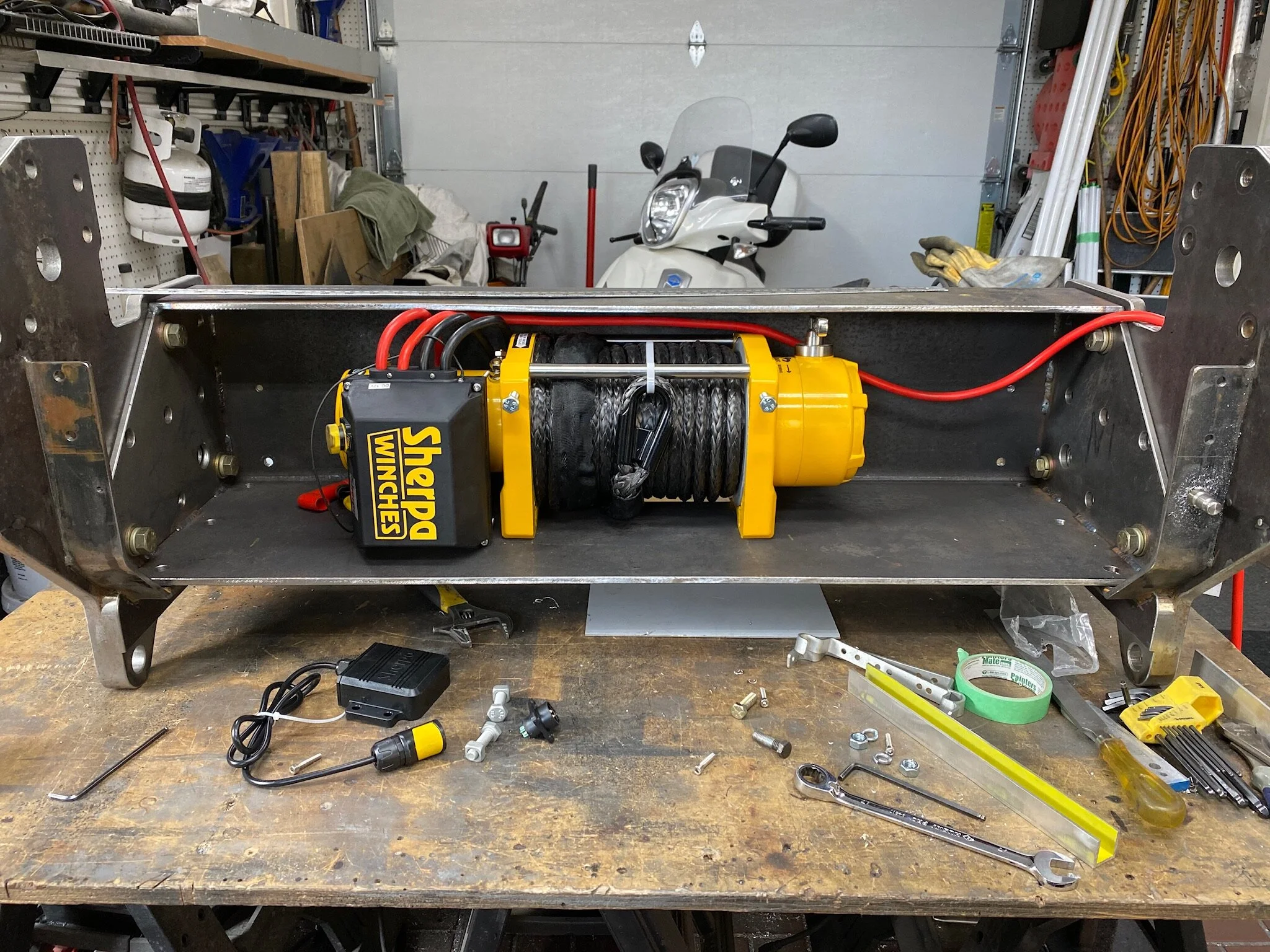
Fitting the Winch
With all of the bumper parts completed, the final step before sending the steel out to be sand blasted and powder coated was to fit the winch into place. The Sherpa4x4 Stallion winch was bought from Australia where it is made. It’s durable, no frills winch with over 25,000 pounds of pulling power. Used with a military block and tackle, it is capable of moving up to 180,000 pounds. More than sufficient for our needs. Since the bolt holes for the winch had already been drilled when the winch channel was made, all we needed to do was make a couple of small brackets to hold the solenoid.


Final Bumper Parts
Here are all the bumper parts ready for sand blasting and powder coating.
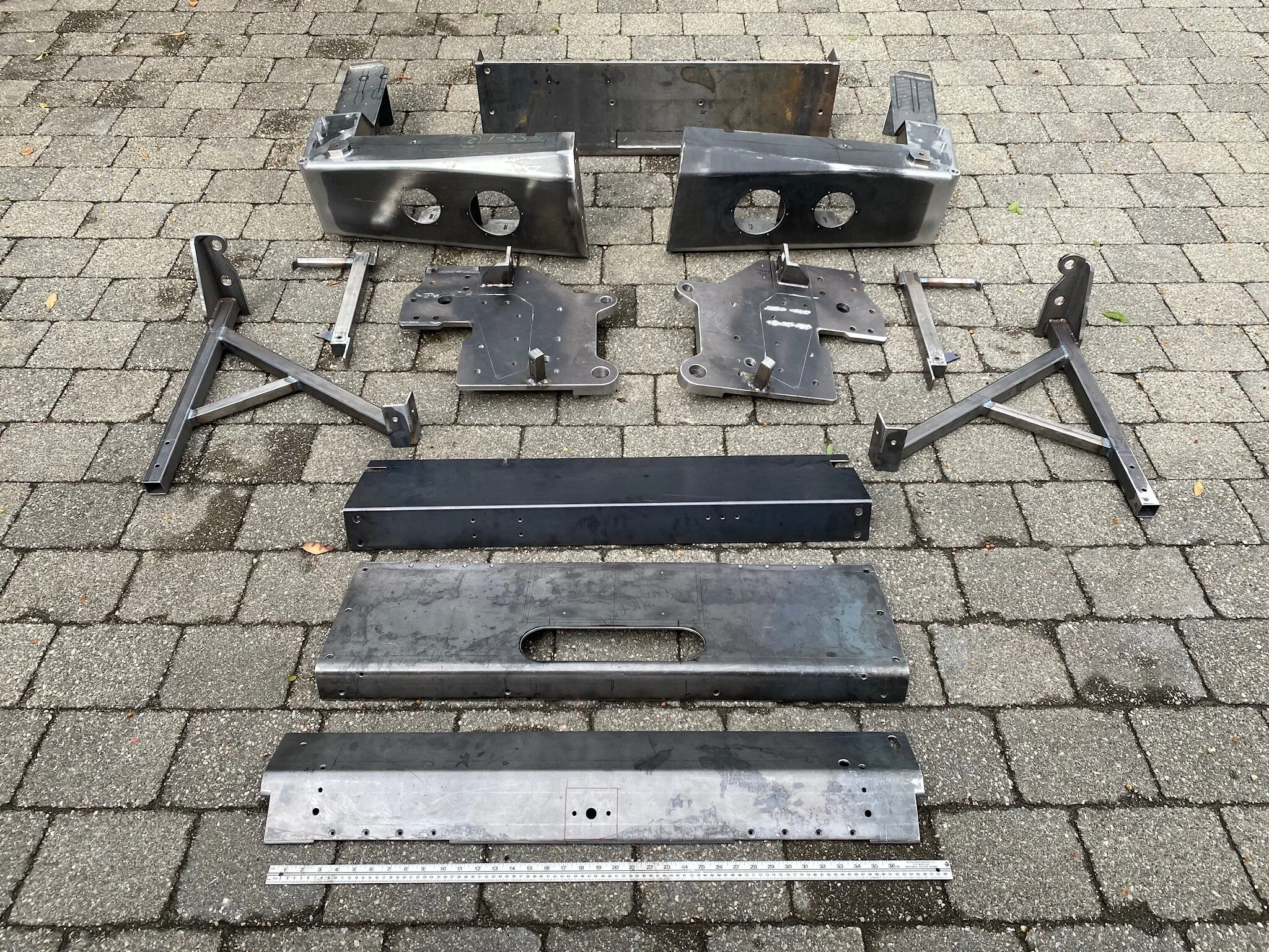

All of the steel bumper parts after sand blasting, and ready for powder coating.
Post Paint Work & Assembly

Turn around time for our powder coater was about ten days. Much sooner than we expected considering the amount of work on his floor when we delivered our parts. All in all, the powder coating job was pretty good. Not perfect by any means, but we’ve had much worse. By the time all things are assembled, the imperfections will be much harder to see. Plus, one trip to the Arctic will do substantial damage to the bumper paint job that it will all be a moot point.


Coating Parts With Rock Guard Coating
Before certain parts could be assembled they needed to have various surfaces protected with an anti-chip coating such as rocker panel protection spray. This included the inside of the bumper corners where rocks flung up from the tires would hit hard, and the inside of the winch compartment where steel tools etc. might chip the powder coating if impacted hard enough. Fortunately this procedure can be done by us with a product bought from the local Canadian Tire store. Dispensed from a rattle can, this product is easy to apply, and etches itself into the powder coating, so no surface prep is required.


Component Pre-Assembly
With the rocker guard spray applied, we could turn our attention to the pre-assembly of certain components. Chief among these was the swing down step of the bumper corner unit.
Assembly of these components is so much easier to do on the work bench as opposed to doing it after the bumper is installed on the truck.


Final Mounting of the Bumper
After months of design and fabrication, we finally arrived at the point of mounting the bumper on the truck for the last time.
Despite the late time in the year, some early November sun and warmth made the installation a much less onerous task.