
Cabin Protection Rails
Something we Planned right from the beginning
If one looks at the original concept rendering that I created, the cabin protection rails are clearly visible. We’ve always known that sturdy protection rails would be needed, especially where we will be using the truck a good deal of the time. Our neck of the woods quite literally has an abundance of trees, and trees can be very hard on roof mounted equipment. Especially glass solar panels. And despite ones best efforts, it’s not always possible to judge the height of branches when they are starting to get close to the height of the truck.
Obstacles Created By the Build
Even though the information that we supplied to the builder clearly detailed the roof rails that we would add ourselves at a later date, the builder ignored it and placed mounts on the edge of the roof in locations that were in conflict with where we wanted to place the rail mounts. Because of this, we had to modify the way we were going to build the rails, and configure the mount placement so that they would not only miss the solar panels mounts, but also look symmetrical. Fortunately, we did manage to accomplish this.
This is the base layout design drawing we used to figure out the foot spacing.
Materials and Design
We wanted to maintain a consistent look with all that had been created so far. So unlike most expedition trucks that have round tube roof rails, we elected to build ours out of square tubing instead. We felt it would blend in with the body lines of the camper much better, and it would match the lift platform on the back of the truck.


One of the considerations we had to decide on was what colour to make the rails, and more importantly, what colour to make the feet that attach to the camper box. Most roof rails are an accent colour, and the feet match the colour of the rails. This makes them really stand out on the box, something that really didn’t appeal to us. We knew the rails themselves would be the same brown colour as the rest of the metalwork on the truck. But did we go with body coloured feet, or rail coloured feet? To help us make the decision on the foot colour, we turned once again to the Photoshop, and created images of both versions of the rails with the different feet colours.
We were pretty sure which one we liked best, but just to be sure, we sent out the two images to a number of trusted friends, to get their feedback. Of the eight people that responded, seven liked the body coloured feet, and one preferred the brown feet. So the verdict was almost unanimous. Most chose the version we ourselves liked the best.
Method of Construction
Section View of Rail System
Unlike most roof rail construction, which is an all welded design, we chose a different approach. Our design is one made of assembled components that are bolted together. The advantage of this is that it makes painting the feet a different colour than the rails much easier. But more than that, the modular design offers a superior end product. There’s no distortion of the rail because of the welding, the parts can be made to a higher precision tolerance, and if any rail or part is damaged because of an impact strike, it can be easily removed and repaired or remanufactured.
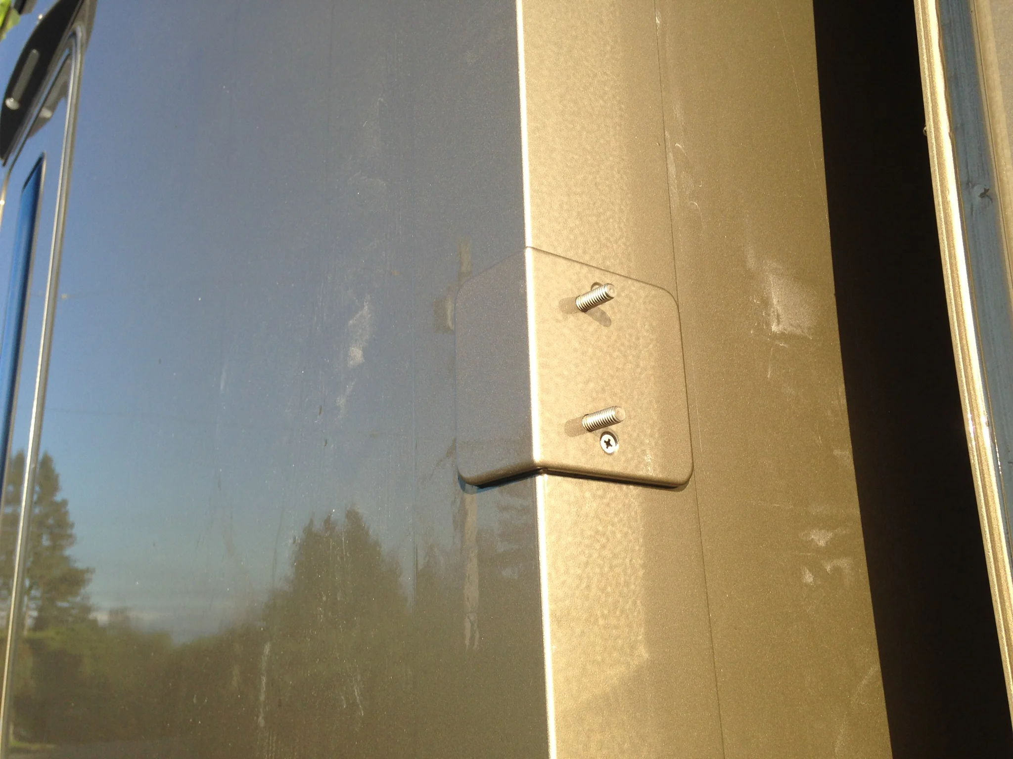
Our design allowed for larger feet than typical, and this has the benefit of a larger glue surface, so added strength. Although some truck builders use mechanical fasteners to attach the feet to the box, we have used a urethane glue product for the main adhesion. We did use two small wood screws on each foot, but these were simply to provide a finite location point that wouldn’t allow the foot to creep out of place while the glue was curing, and the screws were also used to pull the foot down onto the surface to create a uniform gap between the underside of the foot, and the fibreglass edge angle that holds the box panels together. Small pads located under the foot provided the gap spacing so every foot was the same, and the foot itself was glued square and parallel to the edge of the box.
Rail Design

Large gaps like these are a real liability.
A concern we had when looking at roof rails on other trucks was the gap that often existed between the various rail segments. These gaps could allow branches that are sliding along the rail to drop in between them and get caught. The subsequent damage that might occur as the truck continues to move could be of some consequence, and might even rip the rail completely off the truck. Of course if the gaps were very small, then the branches that might get caught would also be small, and may not be a problem. But we didn’t want to take that chance.

Our insert design still allows each section 1/4” for rail expansion due to thermal variation.
So in our design we incorporated inserts that spanned the joints between the rail sections. These inserts serve several functions. First, they do indeed prevent anything from getting caught between the rail sections. But more than that, they increase the strength of the rail system because any force exerted on one section is distributed across a larger area. The open ended design of our rails, which facilitates the use of the inserts, also allows the rails themselves to be used as a continuous wire chase for electrical lines, camera cables or whatever. It gives a us a fully enclosed raceway that stretches the full length of the camper box. So adding future electronics or accessories is quite easy.
The Build Progression
Step 1: The Feet
The painted foot ready for install. Vinyl tubing was used to mask the studs from the paint, and also provided a method of hanging the feet during the painting process.
As with most things, we have to build from the bottom up. And in this case, that’s the feet.
For the best geometry when it comes to attaching the feet to the cabin, an angle was best. This way it has three dimensional shape for maximum strength and rigidity, and creates two glue planes by which to secure it to the cabin’s edge angle.
Unfortunately there isn’t any angle available that has the right leg dimensions for us, and a material thickness of 1/4”. To make things more difficult, all of the “off the shelf” angles that are 1/4” thick have an inside radius which conflicts with the sharper corner of the fibreglass angle. We therefore had to create it.
This was done by taking a piece of square tubing with 4” sides and ripping it on a table saw to create two lengths of angle from the one length of tubing. The advantage of this is that the inside corner of the aluminum tubing had no radius whatsoever. After the tube was ripped, it was then cross cut to create the individual feet. Drilling, shaping and fastener installation came next.


Step 2: The Riser Blocks
Unlike most welded rail installations where the standoff legs are made of the same tubing as the rails, our design uses solid material riser blocks which facilitates the use of mechanical fasteners. From an aesthetics perspective, we feel they add something positive to the overall look as well.
Although the riser block is not a terribly complicated component, it nonetheless had a number of steps to complete it.
Made from solid 1” x 1-1/2” aluminum bar stock, it would get powder coated the trucks brown accent colour.


Step 3: The Horizontal Rails
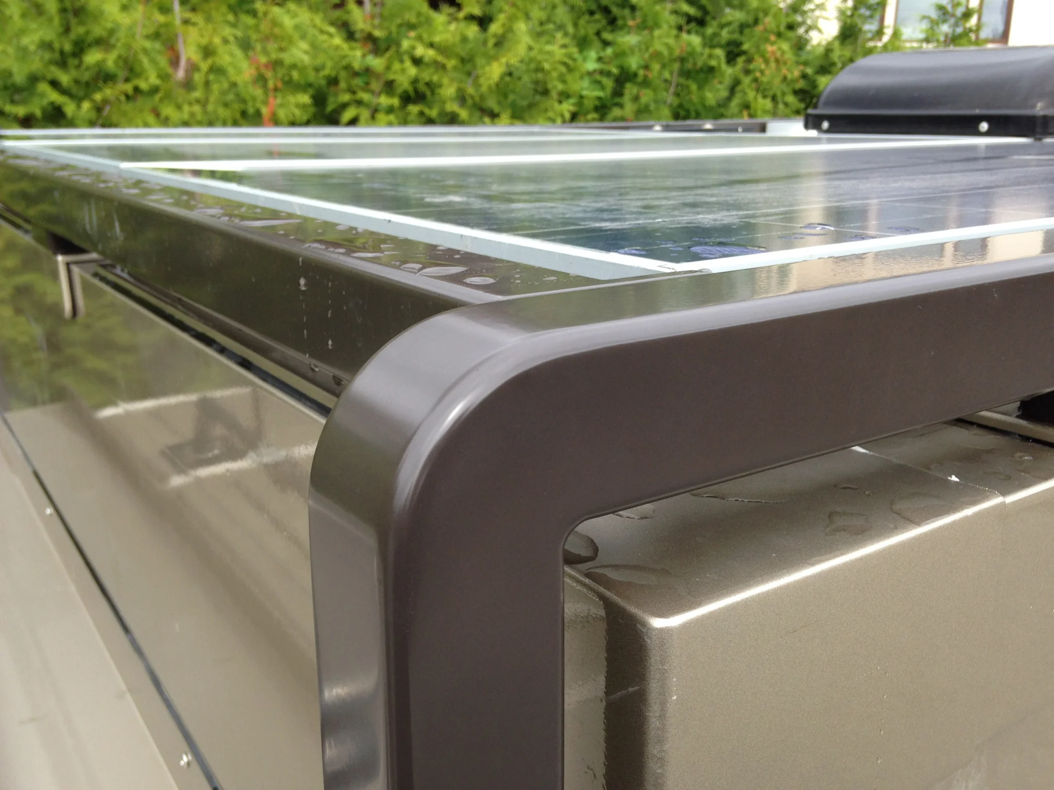
A continuous barrier of protection for the glass solar panels.
Our material of choice for the rails themselves was 2” square x 3/16” wall aluminum tubing. It’s the same material we used on the lift platform for the motorcycle, only not quite as thick a wall dimension.
Aside from it matching the look of the rear lift assembly, we felt from an aesthetic perspective, the square shape of the tubing blended in better with the angular lines of our truck. After all, there’s very little in the way of round shapes on our truck.
We chose the 3/16” wall for resistance to impacts, and although thicker than most other truck rails, using aluminum kept the weight down to the acceptable level of 1.6 pounds per lineal foot. As a comparison, 2” round stainless steel ornamental tubing with a .080” wall thickness weighs 1.7 pounds per foot.
The other advantage of using square tubing over round tubing is the superior resistance to denting from impacts on the top outer edge where most strikes will occur. Unlike a round tube, the 90˚ corners of the tube provides a point that is extremely hard to dent, especially by anything organic.
The length of the various rail sections was largely dictated by the obstacles we had to contend with on the outer edge of the camper box. Since we wanted the joints between the rails to fall within six inches of a mounting foot, and the rails had to be a maximum of eight feet long so as to fit in the powder coating oven, we ended up with four different lengths to span the distance.
Since all of our creations happen at our home, which is located in a residential community, none of the metal suppliers would ship the tubing to us on their large delivery trucks. So we had to go and get it. So using our trusty Land Rover, we headed over to the opposite side of the greater Vancouver area to collect the 20’ long material.
Once back home, the fabrication process began again in earnest. The horizontal rails were the easiest to create because they were essentially just cut to length and then drilled to provide the anchor points.
The exception to this were the two rear sections of rail that had to be closed off, and a unique mounting foot welded on to interface with the rear tire rack and motorcycle lift assembly. After all is said and done, the rear rail sections were actually a structural anchoring mechanism for the rear lift. Their placement distributed the rearward forces exerted by the lift, to the horizontal fibreglass angles glued onto the length of the box. Those angles would be virtually impossible to tear off the box. So they provided the perfect anchor for the entire rear lift and spare tire assembly.


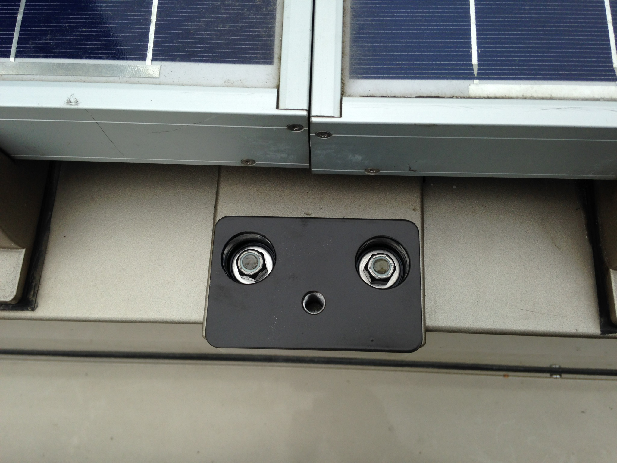
The other operation needed on two of the horizontal rails was to create the cutouts to clear the two solar mounts that protrude into the space occupied by the rail. Although there are various ways of machining these cutouts, because there were only two of them, we did them by hand with a drill and jig saw. Clean up was done with a file.


Step 4: The Vertical Rails
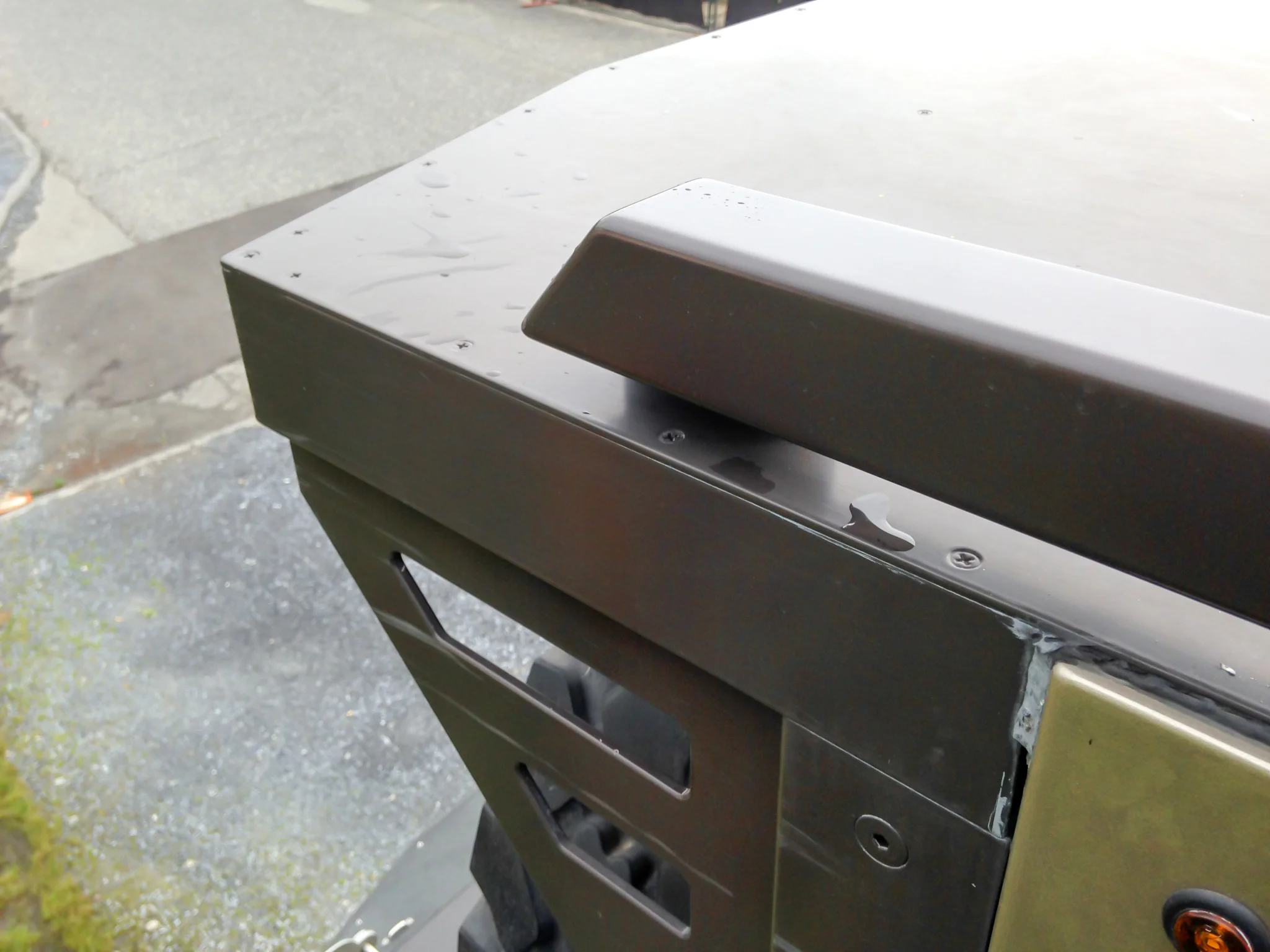
The two front vertical rails are where the most work was centred. They had to interface with the top horizontal rails, as well as the front cross rail that joins the two sides together, and which adds the superior strength to our design.
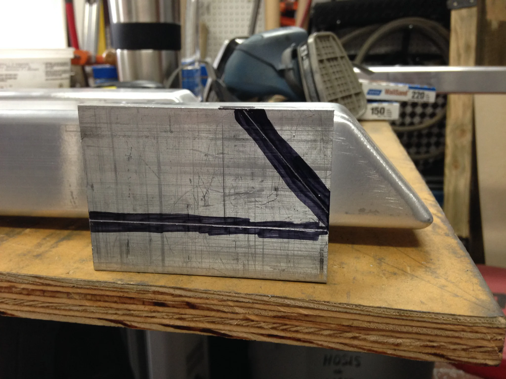
What created the most work on these rails were the two 90˚elbows. Unlike round tubing or pipe, where weld on elbows are readily available for purchase, no such elbows exist for our choice of square tubing with the edge profile and material thickness that we are using. So we had to create the curved appearance that would compliment our design. This in itself was a very time consuming process, but the end result was well worth the effort.


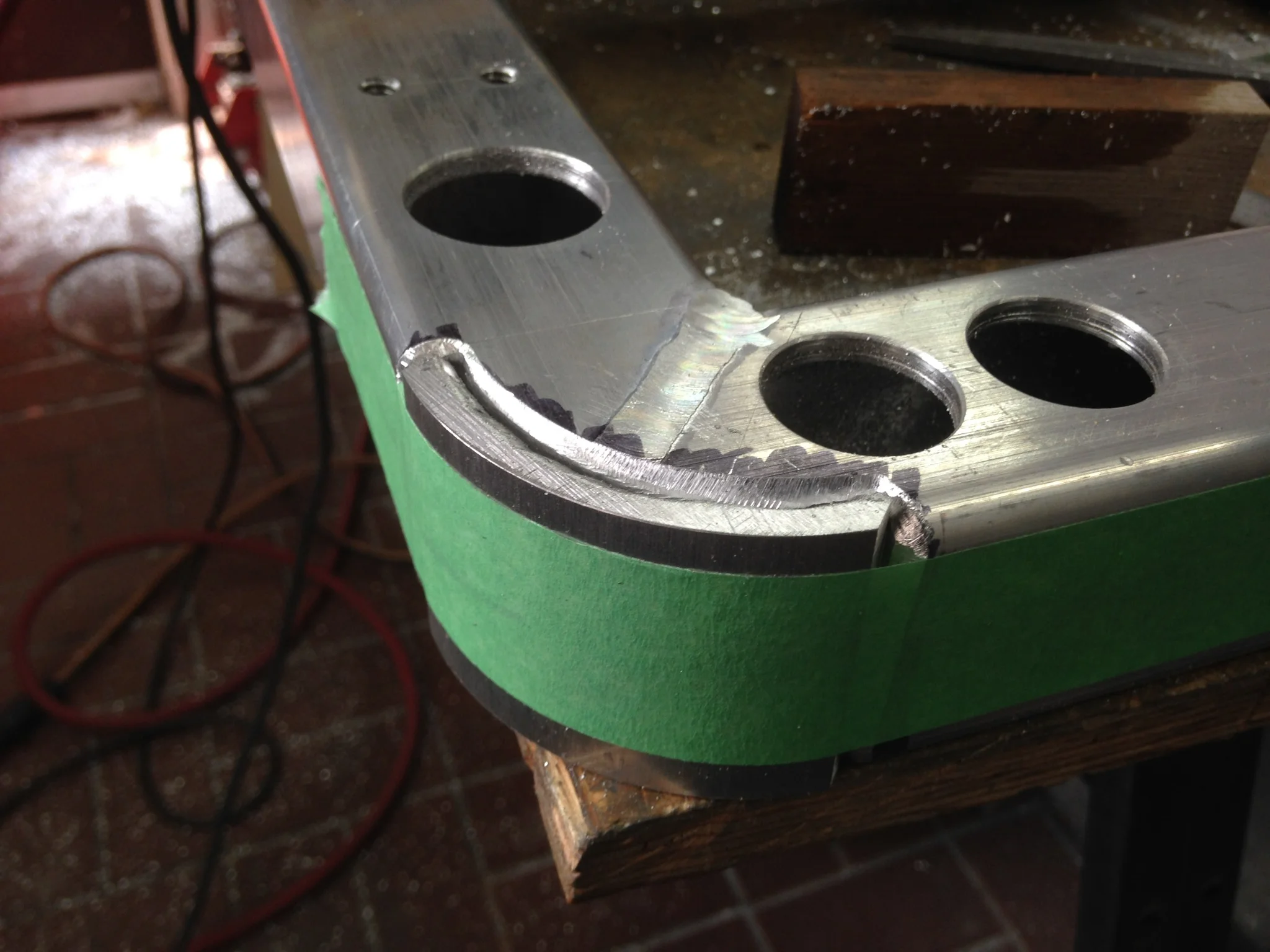


Once the fabrication was complete, the process of dressing down all the welds and giving the corner its final appearance began. The first step starts with the router and a flat ended carbide bit.


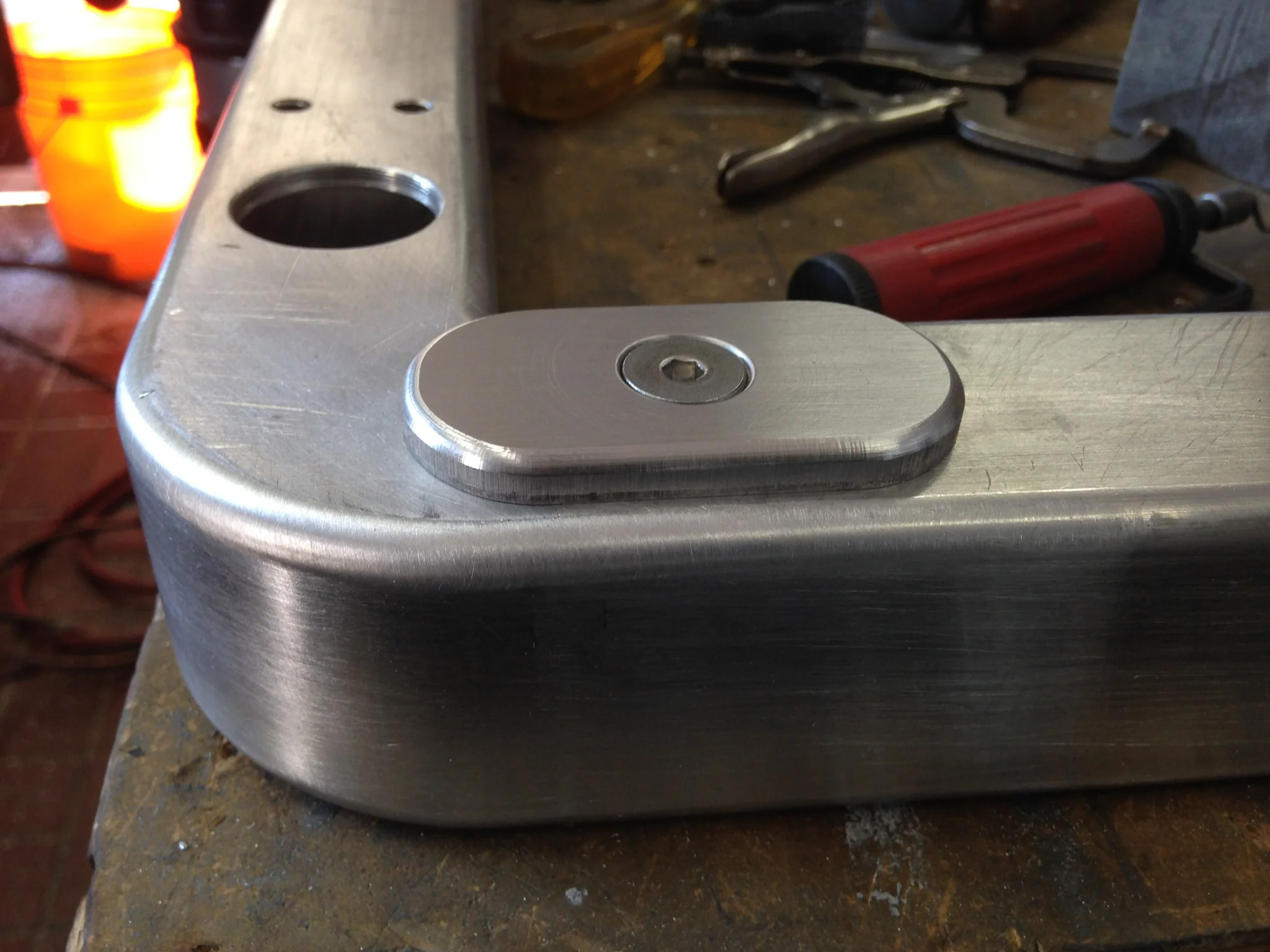
To complete the cabin rails we next had to manufacture the inserts and cover plates for the wire chase openings. Nothing too difficult, just fussy work.


Step 5: Preparing the rails for paint
Raw mill finish on the left, abraded finish on the right.
Before sending the parts out to be painted, the surface of the aluminum must be prepared. The raw aluminum mill finish does not allow the powder coating to adhere very well. So the surface must be abraded to create a key for the coating to lock into.
The small parts like the feet, riser blocks and cover plates were sent for sandblasting. But the tubing had to be treated differently. Sandblasting is an aggressive process, especially when done by an industrial sandblaster. The forces exerted on the material can have an effect on the structure of the metal, and things like long lengths of aluminum tubing can be easily warped. We certainly didn’t want that for our nice straight rails.


Step 6: Rail Installation
The actual installation was an involved procedure, mostly because we wanted to do it right.
The first step was to accurately lay out the position of the feet. This was necessary because we had to sand away the paint in order to create a proper bed for the Sika urethane primer and glue.
To aid in the sanding procedure, a plywood template was made that wrapped over the edge of cabin and could be taped in place. The vibrating sander we used on the edges of the aluminum tubing could now be used to sand away the layers of paint.


The sanding took quite a bit of time. All twenty two spots needed to be well done in order to have not only the glue adhere well, but the primer as well. Unfortunately the overhanging solar panels meant that some sanding had to be done without the aid of a machine.


The process of applying the glue from a caulking gun went quickly, but the cleanup afterward took longer. We wanted to be sure that lots of glue was initially applied so it would ooze out all around the foot. We didn’t want any air bubbles under the plate, or voids at the edge that would need caulking afterwards to fill the missed spots.


The last thing to do before the job was totally finished was to paint the plugs that would close off the holes for the railing bolts. We only had black ones, but wanted them to match the colour of the rail powder coating. Fortunately the powder manufacturer also makes matching rattle can spray paint. All we had to do was spray the plugs with a plastic adhesion promoter, and then we could apply the colour coat.


The finished rail installation hides the solar panels from view and elegantly frames the cabin.