Bull Bar
Increased Collision Protection
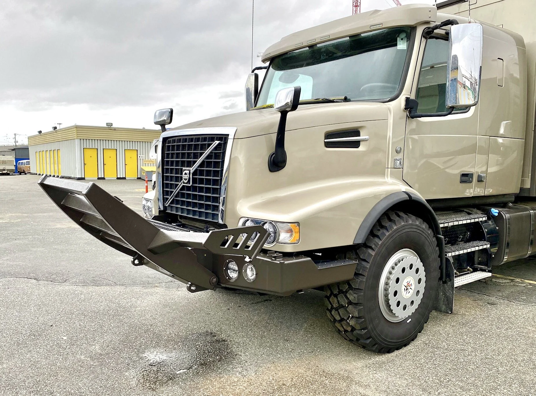
Although the top of our newly fabricated front bumper stands a full three feet off the ground, road hazards exist that this bumper on its own can’t fully protect us from. We’re not talking about those made of metal and polymer, but rather those often unseen obstacles of the flesh and bone type.
This graphic shows the size relationship of a mature bull moose in front of our truck.
Many parts of the world have hazards from the natural world that pose a significant risk to vehicle travel. For many people, they think of Australia with large red kangaroos bounding across highways and colliding with vehicles. In those cases, the largest wandering roo might weigh as much as 90 kilograms (200 pounds) and stand 4 to 6 feet tall at the top of the head. But the reality is that in areas like North America and Northern Europe, much larger animals exist and wander the landscape at will. Dwarfing the largest kangaroo, moose can stand as high as 2 meters at the shoulder and weigh over 500 kilograms (1200 pounds). Other large animals include elk, caribou, bear and bison.
Even the largest truck when confronted with a large moose inside the braking limit of the vehicle will suffer catastrophic damage if not adequately protected. But even with this extra protection, significant damage is guaranteed. The objective, however, is to keep the vehicle in some form of drivable condition so it can make it to a population centre where help can be secured. This is the reason we designed and built a substantial bull bar to compliment our heavy duty steel bumper.
Design Considerations


We went through several design iterations in the process, mostly trying to follow the unique look of the grill on the front of our Volvo VHD. Unfortunately, to make the bull bar with the outward leaning vertical posts just wouldn’t work. The width of the frame rails was such that we would be starting from a width at the bottom that would make the top of the bull bar far too wide, and would look odd. It would also mean a joint where the vertical posts bent outward, and this would seriously compromise the strength.
We also ultimately decided to go with horizontal cross rails as it tied the two verticals together better from a structural perspective. We also added the diagonal to the grill area so as to match the signature look of the Volvo identity. It also adds a diagonal gusset to help eliminate a parallelogram deformation if the bull bar is struck on the end of the outrigger bars.
The Fabrication process Begins
Here are the water jetted outrigger end plates and their two foot plates.
Outrigger bar end plates
Since the bull bar, like the bumper itself, was being built in our garage with limited equipment, we chose to have the outrigger arm end plates cut out by the same water jetting company that did the bumper brackets. The reason for this is that these end plates were made from 3/4” thick 6061-T6 aluminum plate and would have decorative horizontal slots to match the aluminum lift platform on the back of the truck. Although I could easily cut the outer shape myself, the slots would be time consuming if a proper job was to be done. We’d also have to find the aluminum plate, which in small pieces is expensive when bought from a metal retailer. The water jetting company keeps this material in stock, so it was much easier, and indeed cheaper, to just give them the .dxf file for these parts and let them supply the material and do the work for us.
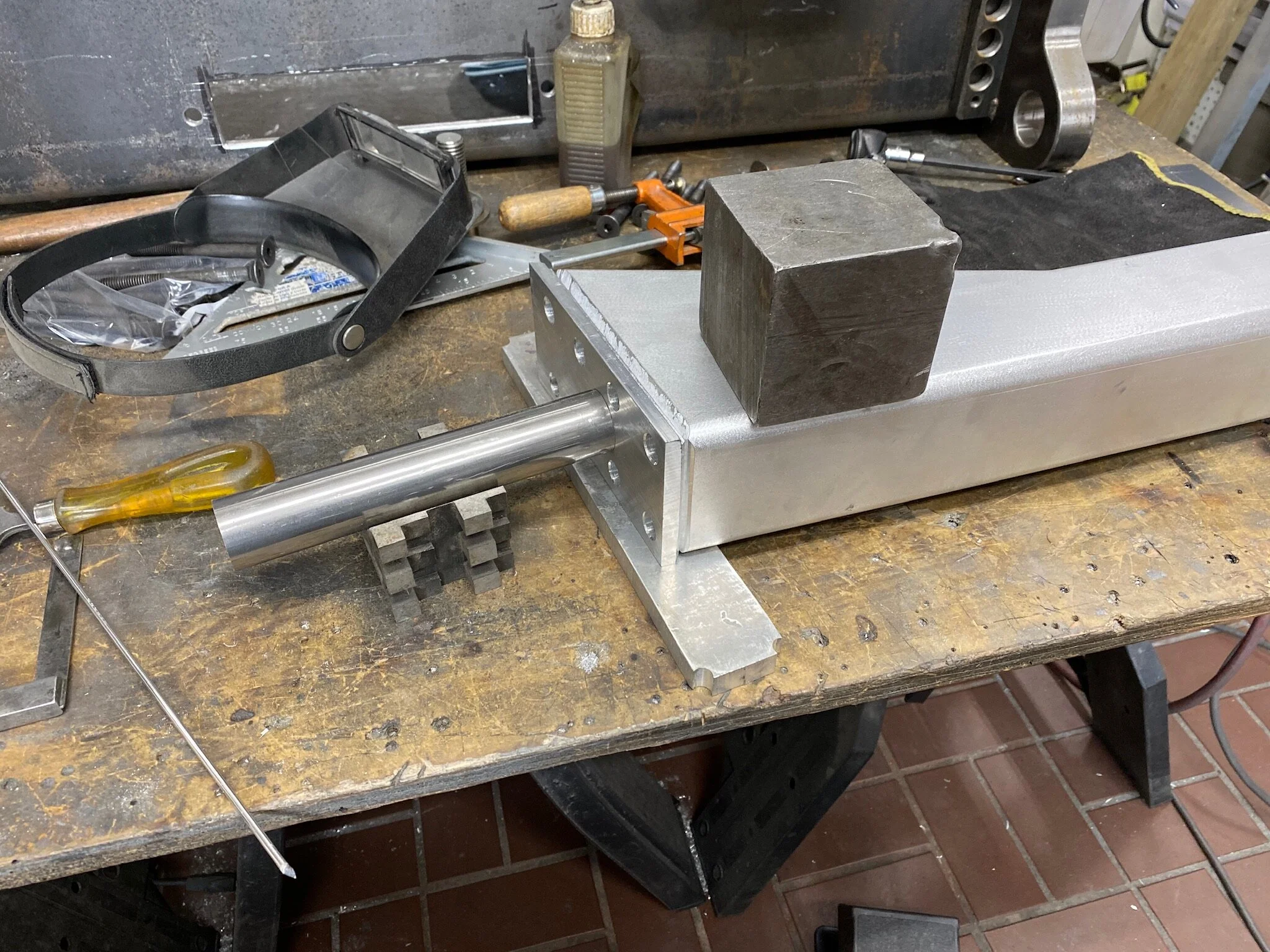
Here are the finished end assemblies prior to welding the foot perimeter.
Once we got the plates back, it was a matter of dressing them up and then attaching the foot to the vertical plate. The connection was done both with fasteners and weld. Since this end assembly was a structural member of the bull bar, we wanted a secure attachment. Something we didn’t want to rely solely on the weld to perform. After all, it is an aluminum weld, and not very large.
Dressing was done first by draw filing all of the inside surfaces of the slots. This eliminated any stop/start rough points from the water jet cutting. Then, by using a router with a round over bit, all the sharp edges were shaped to radius all the corners. After this, the routered edges were lapped with a hand abrasive cloth to smooth them out, before sanding the faces with an orbital sander.


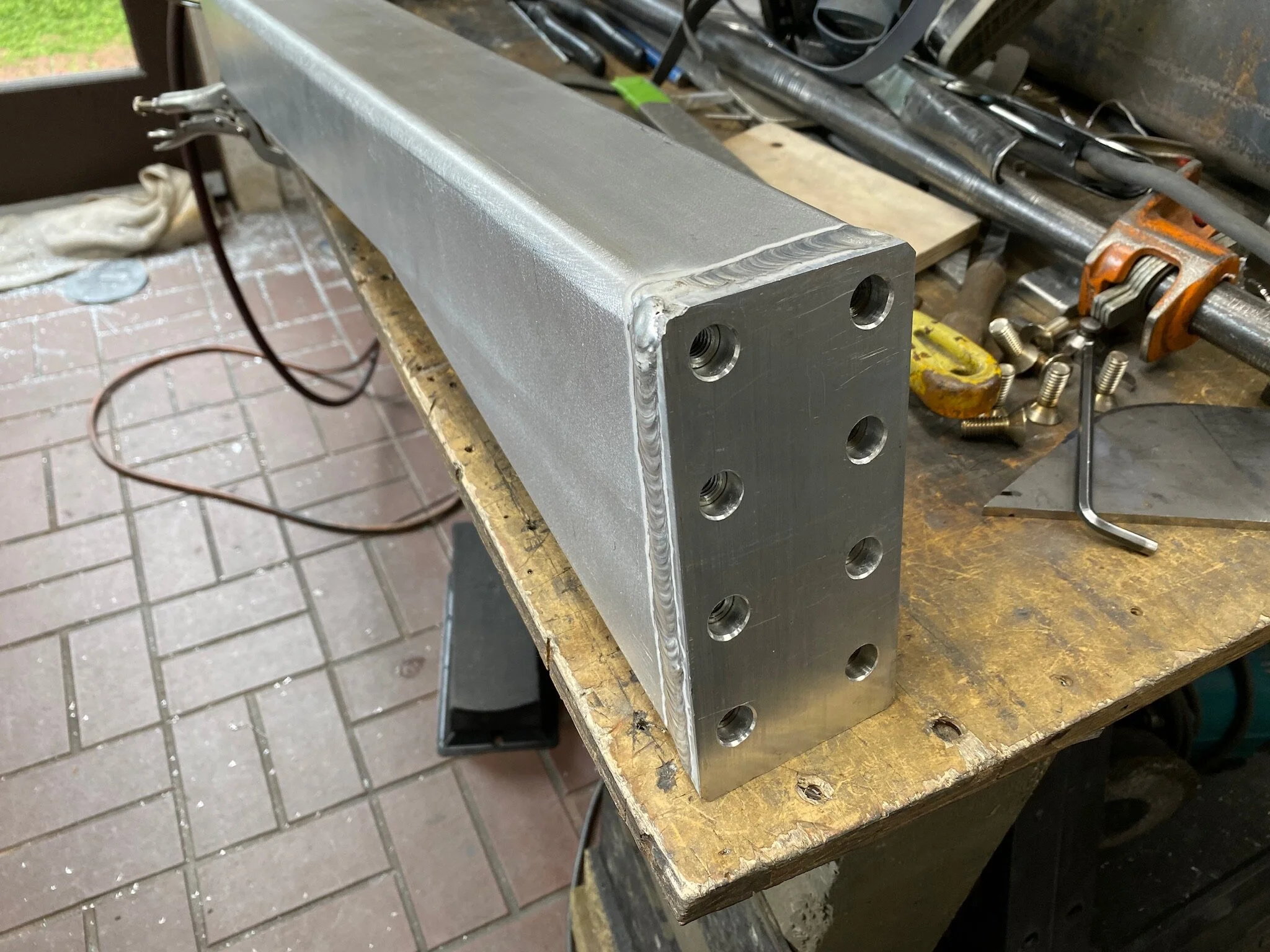
Securing the feet
Since the joint between the side plate and foot is a structural one, we took extra care to ensure the joint would remain intact in the case of an impact. To this end, we used both mechanical fasteners and tungsten inert gas (TIG) welds.
One of the advantages of using the mechanical fasteners is that it is a more precise way of securing things than trying to just clamp pieces together before a weld process. Eliminating the clamps also makes the welding process a lot easier. The fasteners we chose are a grade 10.2 flat head 3/8 fine thread machine screw. They thread 1-1/4” into the vertical plate, and we used six of them in each assembly.


Main Vertical Posts
There are different ways of designing the main structural component of a bull bar. Most of the bull bars that are made today consist of a heavy vertical flat bar with a thinner flat bar strap wrapped around it and welded to it to give it three dimensional thickness. It’s a quick and inexpensive way to build a bull bar. But it’s not the strongest design, nor does it have the most appealing appearance.
The higher quality, higher strength commercially made bull bars are all made with a box construction vertical member of differing shapes. Unfortunately, these bull bar/bumper combinations are expensive. They’re worth the money, but it certainly hurts the old pocketbook.
Since we are making our own bull bar, and our hourly shop rate basically boils down to coffee and cookies, we elected to go the more time consuming route of a shaped box section vertical. Above that, we decided to shape it to compliment the front profile of our engine hood.
To create the shape we used 1/4” thick 6061-T6 flat bar. The sides came from 8” wide material, and the front from 2-1/2” wide material. The back face was developed from 3” channel, as it was needed for structural reasons.
The first step to creating the vertical posts was to print out a full size graphic of the post layout. This way we could easily transfer the curved shape of the post front onto the aluminum flat bar. It also gave us all of the attachment points without having to transfer each individual measurement.


Vertical Post CoNstruction
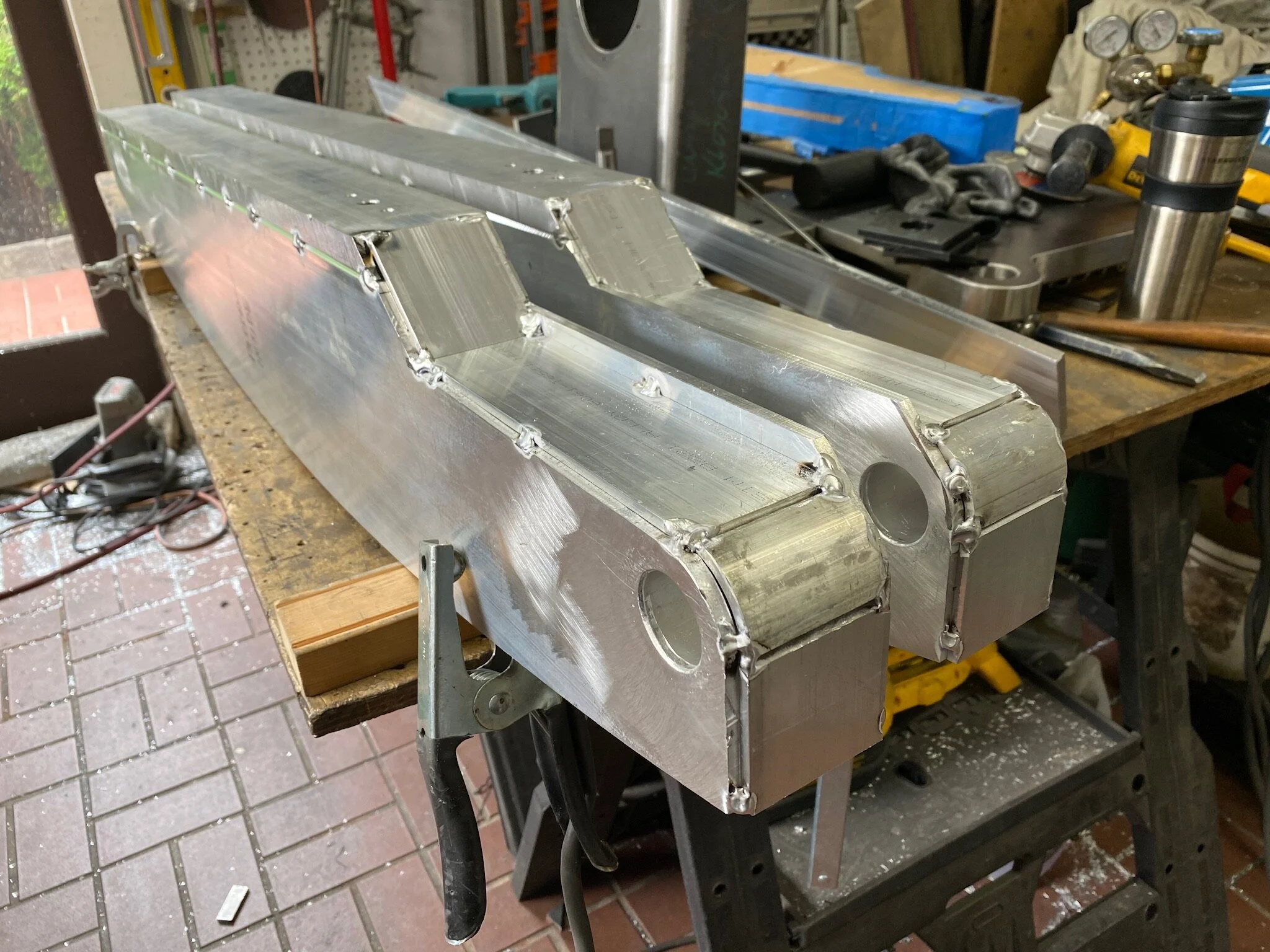
Now that the post sides are finished, it’s time to start constructing the post’s three dimensional shape. This begins by laying out the placement of the internal components. These components consist of the pivot tube at the bottom of the post, along with three braces made of aluminum square tubing.
The aluminum braces do several things. First, they provide the spacer to position the two side walls a precise distance apart so the perimeter strips can be welded in place. Secondly, they provide additional structural strength against sideways impact deformation by transferring the forces through the width of the post, and then by the cross rails to the other side of the bull bar. By doing this it reduces the chance that the perimeter flat bar welds might fail.


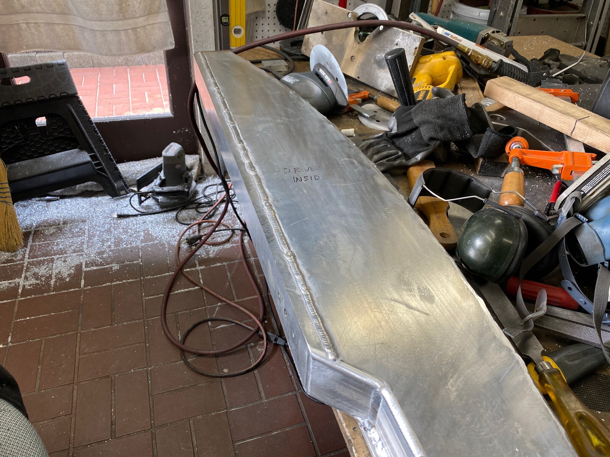
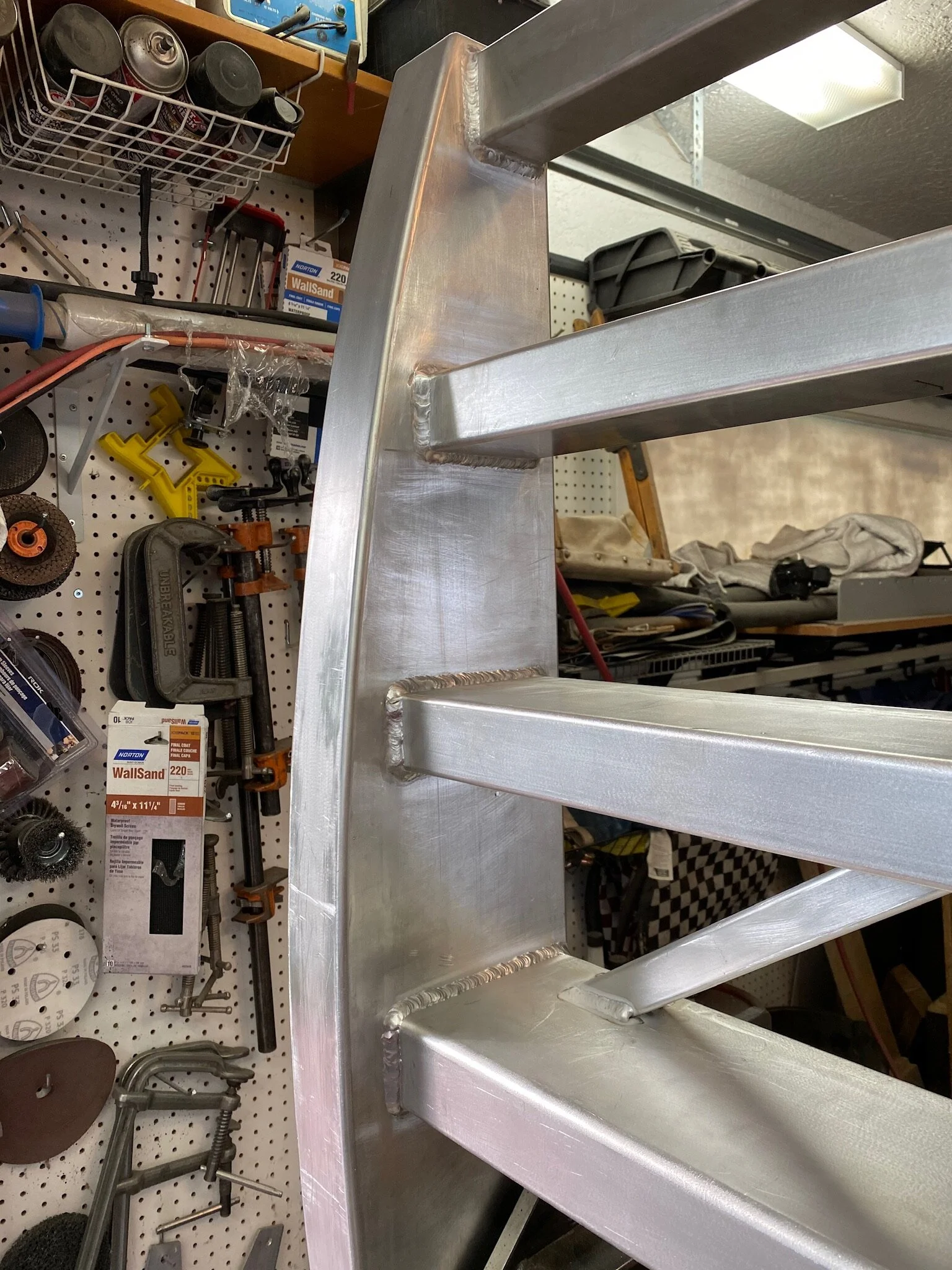
After all that welding, you can’t get much straighter than this.
Adding the vertical post perimeter
With over 16 feet of continuous weld per post, care must be taken to balance the stresses in order to keep the post straight.
Perhaps the trickiest part of the whole build is attaching the perimeter flat bar to the post assembly. This is because it’s welded in place, and so much weld, if not done correctly, can create tremendous stress in the structure which shows up as unwanted distortion. The preferred and necessary straight vertical post could end up looking like a banana.


Vertical Post Weld Dressing
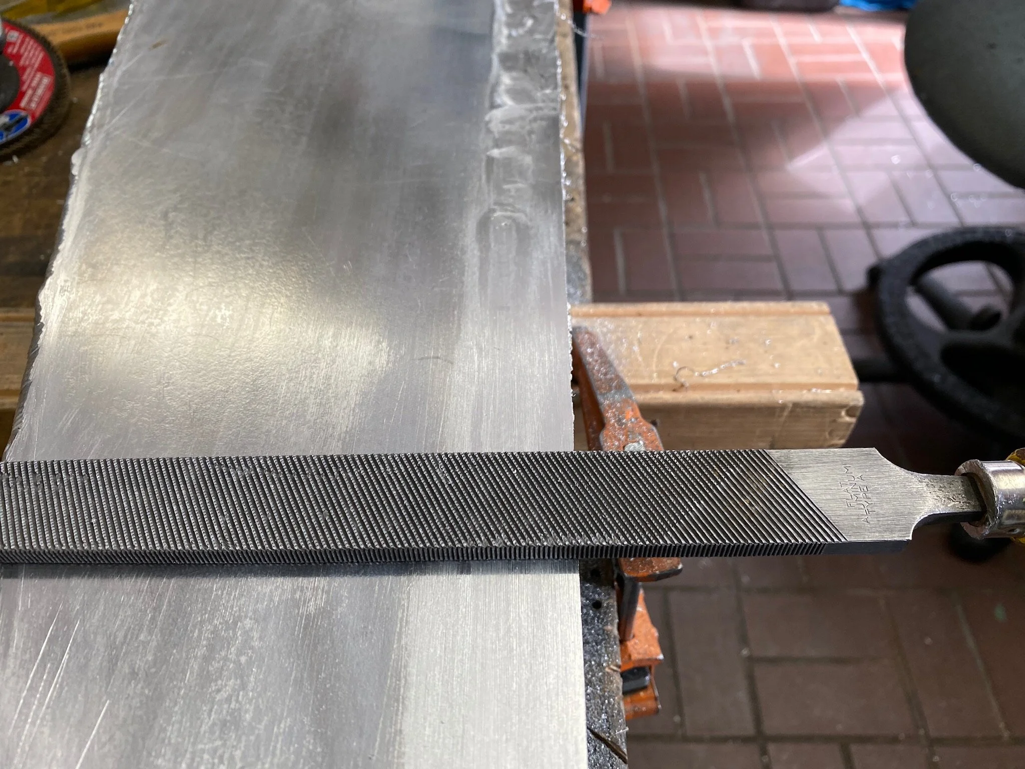
A before and after image of weld dressing and surface sanding with an orbital sander.
After the welds were all completed, they all needed to be dressed to make them disappear. The objective was to make the structure look seamless, like it was not a fabricated component.
The primary tools for this kind of work, on aluminum, is a hand router with a flat end, chamfer or radius carbide cutter, a coarse and fine flat file for draw filing, various lengths of abrasive cloth in a fine grit, and an orbital sander with 100 and 150 grit sanding disks.

The first job in the dressing is to make the side faces smooth and level so the router base plate can run easily along it to radius all the corners. To accomplish this we have to customize the router baseplate so it will run along the smooth side of the face while the flat end of the cutter can remove the top of the weld bead.


Creating the bull bar cross rails
Paper cutouts show the size and location of the cross rails.
The next job in building the bull bar is to create the cross rails. Now this might not sound overly complicated. After all, the cross rails are just rectangular tubing, right. Well, not quite. You see, the bull bar verticals change dimension front to back, as measured from top to bottom, and we wanted the cross rail depth to be spaced evenly. So to do this we would need to use rectangular tubing of differing dimensions. Unfortunately, for perfect spacing, the tubing sizes we wanted don’t actually exist. This meant we needed to actually fabricate two of the four cross rails.
The top two rails were simple enough, as they were standard tubing sizes. But the bottom two rails had to be created from other parts. The third rail was fabricated from two pieces of rectangular tubing. One cut down along its length and then the two welded side by side. The bottom rail, however, had to be made from four pieces of flat bar the way the vertical posts had to be done.
Third Rail Construction - this rail was made from one piece of 2”x2”x3/16” tubing and one piece of 2”x4”x3/16” tubing. The 2”x2” tube was cut lengthwise into the shape of a “U”. Then the two were welded together and dressed down.


Fourth Rail Construction - The fourth rail dimensions needed to be 2.5”x6.5” in cross-section. To get this we used 1/4”x6” and 1/4”x2” flat bar, and to space the pieces accurately we used some 3” aluminum channel as internal braces. This kept the developed tubing from distorting into a parallelogram from a rectangle, because of the welding stresses.


Drilling The Cross Rails - The last procedure on the cross rails was to drill in all of the various holes we needed. Some holes were used for attaching the wire chase channels to the back in order to hide any wiring we might want to add for lights or whatever. Other holes we added to fasten snaps so that radiator grill covers, mesh for summer bug protection and solid material for winter cold protection, could be attached as needed. Winter is particularly important because extreme sub-zero temperatures will keep the engine from heating up to proper operating temperature if air is allowed to flow through the radiator and over the outside of the engine surface. We discovered this on our first -25°C trip to northern British Columbia.


Accommodating The Winch Compartment Lock - Since the winch compartment would also store some recovery equipment, we needed to lock it for theft prevention.
To create the lid lock we took a Bolt Lock hitch lock and cut the hitch pin shaft, welding only the locking end to the bumper bracket lid shelf.
Locking the compartment came with one problem, though. The lock we wanted to use was a Bolt Lock hitch lock, which allows us to unlock it with the truck ignition key. The issue is that this lock is on the top of the lid, and this would put it in conflict with the lowest cross bar of the bull bar. So to get the lock off without having to tip the bull bar forward we would have to provide a cut out in the lower rail.


Bull Bar Assembly


Now that all of the parts have been created, the time has come to start welding all the pieces together. Although all the layout was designed on a cad program (a very cheap cad program), mocking up the parts for visual verification was a good double check.
Not only did we need to confirm the rail spacing and front to back position, but we also had to verify that the winch compartment lid, when hinged open, would clear the underside of the lower rail.


Building The Outrigger Bars
Now that the bull bar is assembled, it can be mounted back on the bumper so the outrigger bars can be measured, cut and assembled.
Doing this is a complicated process because of the multiple components that are bolted together to form the completed product, and how the moving parts must interface perfectly with the stationary parts in order for them to be locked in place. This is made even more complicated since the bumper will be disassembled, painted and then reassembled on the truck rather than the bench. So positional irregularities can creep in during installation that might impact the accuracy of the interface points. Bottom line, lots of wiggle room needs to be factored in.
Creating The Horizontal Rail - With the vertical end plate in position and braced at 90°, and a piece of wood clamped to the bull bar vertical at the proper height, the 3” square tubing could now span the gap so the length and end angles could be scribed on the tubing. The tubing was then cut on the mitre saw.


Attaching The Bolt Plate - The bolt plate is what secures the outrigger bar to the bull bar vertical. Made from 3/8” x 3” 6061-T6 aluminum flat bar, it was cut to size with angled ends to match the angle on the various surfaces of the outrigger bar.
Rather than threading the holes in the plate with a tap, we elected to use hardened steel PEMserts, which are pre-manufactured fasteners designed to be pressed into holes drilled or punched into the base metal. They are more precise and far stronger than tapping the holes to create the threads.


Completing The Outrigger Assembly - The final steps in completing the outrigger is to drill the bull bar verticals to accept the cross rail bolt plate, and then weld the cross rail to the end vertical plate out on the corner of the bumper.


Final Pre-Paint Assembly Test
The last thing we did before sending all the parts out for sand blasting and powder coating was to fully assemble the bull bar with the bumper to ensure everything worked perfectly.


Final Installation on The Truck
After getting all the parts back from the powder coater we set about prepping the parts for installation.
Not a lot had to be done other than to add the wire chase channels on the back of the bull bar section, and to add to them the numerous snaps that would be used to hold the bug screen or winter cold cover on when needed.